Editorial Technical Reference

Power Amplifier (PA)

This page explains how Power Amplifier (PA) is classified within Computer, Electronic and Optical Product Manufacturing. Technical values and manufacturer relationships are research references; confirm the current specification and supplier evidence for each order.

Technical Definition & Core Assembly

An electronic component that increases the power of radio frequency signals for transmission.
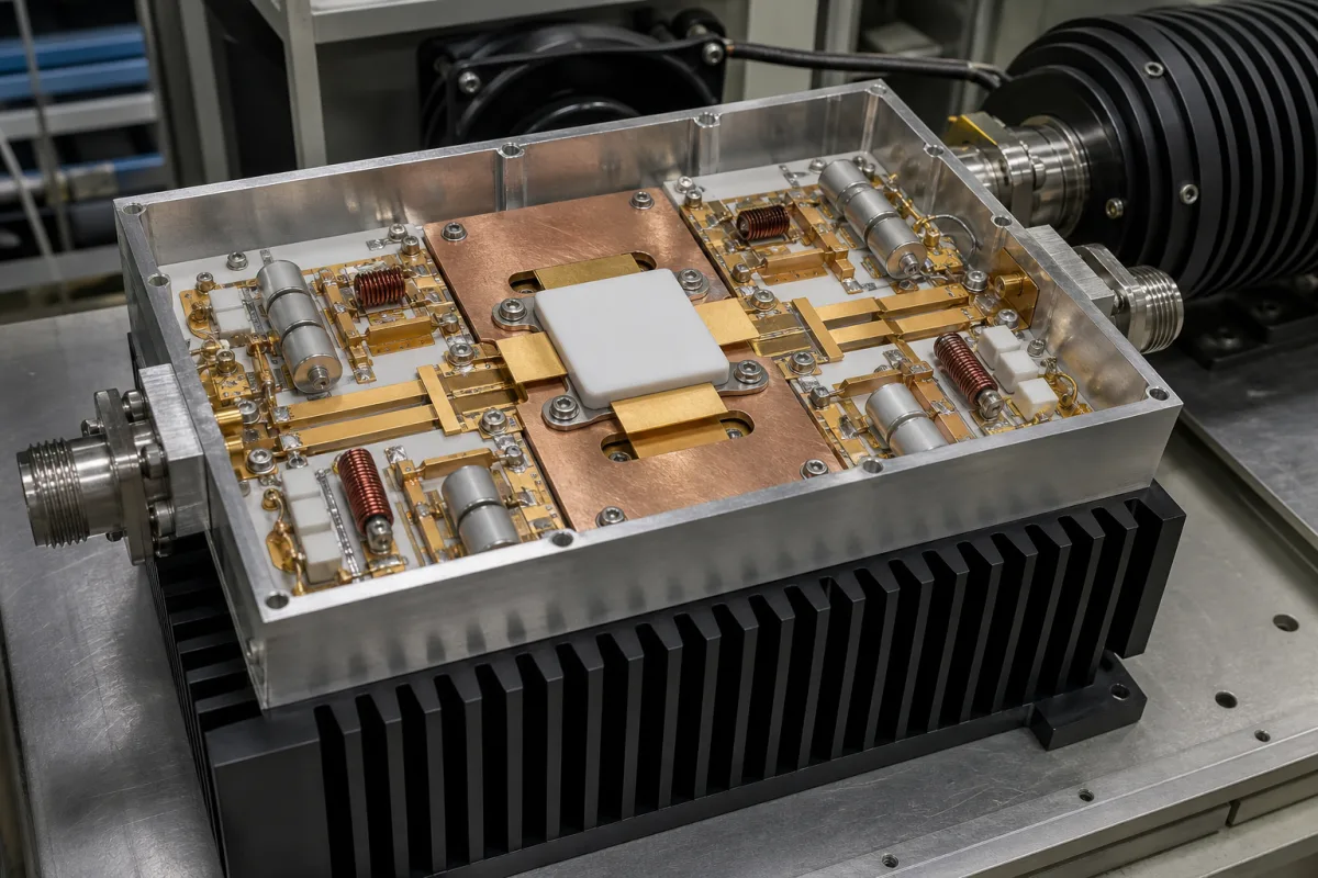
Representative product image. Confirm appearance and specifications with the manufacturer.

Product Specifications

Technical details and manufacturing context for Power Amplifier (PA)

Definition
A power amplifier (PA) is a critical component within a wireless radio module that amplifies low-power radio frequency signals from the transceiver to a higher power level suitable for transmission through an antenna. It ensures signals can travel the required distance while maintaining signal integrity and meeting regulatory power limits. The PA receives a low-power RF input signal and uses active semiconductor devices (like transistors) operating in their nonlinear region to increase the signal's amplitude. It draws power from a DC supply and converts it into a higher-power RF output signal, with efficiency and linearity being key design considerations to minimize distortion and power consumption. Typical materials include Gallium Arsenide (GaAs), Gallium Nitride (GaN), Silicon (Si), and Silicon Germanium (SiGe). Directory reference parameters include a frequency range of 0.8–2.7 GHz, output power (P1dB) of 30–40 dBm, gain of 20–30 dB, gain flatness of ±0.5 dB, input VSWR ≤1.5:1, supply voltage 24–28 V DC, current consumption 2–5 A, efficiency 40–60%, operating temperature -30 to +70 °C, IP rating IP65 (per IEC 60529), input/output impedance 50 Ω, dimensions 150×100×25 mm, and weight 300–500 g. These values are typical reference ranges and must be verified for the specific model and application. The PA is used in base stations, repeaters, and other RF transmission equipment. Its performance directly affects link budget, signal quality, and thermal management. When selecting a PA, consider frequency band, required output power, gain, linearity, efficiency, and environmental conditions. Verify all specifications with the legal manufacturer or supplier before procurement. Maintenance signals include degraded output power, increased current draw, or thermal shutdown. Failure boundaries include operation outside specified voltage, temperature, or VSWR limits, which may cause damage.
Working Principle
The PA receives a low-power RF input signal and uses active semiconductor devices (like transistors) operating in their nonlinear region to increase the signal's amplitude. It draws power from a DC supply and converts it into a higher-power RF output signal, with efficiency and linearity being key design considerations to minimize distortion and power consumption. The transistor's bias point and matching networks determine the operating class (e.g., Class A, AB, B, C), which trades off linearity against efficiency. The amplified signal is then passed to the antenna, while heat generated from inefficiency must be managed via heatsinks or active cooling.
Common Materials
Gallium Arsenide (GaAs), Gallium Nitride (GaN), Silicon (Si), Silicon Germanium (SiGe)
Technical Parameters
ParameterTypical rangeNotes & selection driver
Frequency Range0.8–2.7 GHzCovers major cellular bands; outside range gain drops.
Output Power (P1dB)30–40 dBm1 dB compression point; higher power for longer range.
Gain20–30 dBMinimum gain for system link budget.
Gain Flatness±0.5 dBOver full frequency range; affects signal quality.
Input VSWR≤1.5:1Mismatch causes reflection and power loss.
Supply Voltage24–28 V DCTypical for base station PAs; ±10% tolerance.
Current Consumption2–5 AAt max output power; affects heat and supply design.
Efficiency40–60 %PAE at rated output; higher reduces heat and power cost.
Operating Temperature-30–+70 °COut of range may cause thermal shutdown or damage.
IP RatingIP65Dust-tight and protected against water jets.IEC 60529
Input/Output Impedance50 ΩStandard for RF systems; mismatch causes reflections.
Dimensions (L×W×H)150×100×25 mmCompact module for integration; footprint affects layout.
Weight300–500 gInfluences mounting and mechanical design.

Ranges are indicative industry figures for RFQ preparation, not a supplier commitment. Confirm every value and standard with the legal manufacturer before ordering.

Components / BOM
  • Transistor Array Part
    The active semiconductor devices that perform the signal amplification.
    Material: Gallium Nitride (GaN) or Gallium Arsenide (GaAs)
  • Input/Output Matching Network
    Circuitry that ensures maximum power transfer by matching impedance between stages.
    Material: Copper, Inductor/Capacitor components
  • Bias Circuit Part
    Provides the proper DC operating voltage and current to the transistors.
    Material: Silicon, Resistors, Capacitors
  • Heat Sink Part
    Dissipates heat generated during operation to prevent overheating.
    Material: Aluminum or Copper

Applied To / Applications

This component is essential for the following industrial systems and equipment:

Industrial Ecosystem & Supply Chain Structure

Complementary Systems
Downstream Applications
Specialized Tooling

Application Fit & Sizing Matrix

Operational Limits
pressure: Not applicable (electronic component)
other spec: Frequency range: 0.5-6 GHz, Power output: 10-100W, VSWR: <2:1, Efficiency: >40%
temperature: -40°C to +85°C (operating), -55°C to +125°C (storage)
Media Compatibility
✓ RF communication systems ✓ Radar transmitters ✓ Satellite uplinks
Unsuitable: High humidity/condensing environments without proper sealing
Sizing Data Required
  • Required output power (dBm/W)
  • Operating frequency range (GHz)
  • Input signal characteristics (modulation, bandwidth)

Reliability & Engineering Risk Analysis

Failure Mode & Root Cause
Thermal Overstress
Cause: Inadequate cooling leading to semiconductor junction temperatures exceeding design limits, often due to blocked heatsinks, fan failure, or excessive ambient temperatures.
Output Stage Failure
Cause: Overvoltage/overcurrent conditions from improper load matching (e.g., VSWR mismatch), transient spikes, or driving into saturation/clipping, causing transistor breakdown or bond wire fatigue.
Maintenance Indicators
  • Intermittent or distorted output signal (audible crackling, frequency drift, or reduced output power)
  • Excessive heat emission from heatsinks or enclosure (beyond normal operating temperature) or audible fan noise indicating cooling system strain
Engineering Tips
  • Implement strict thermal management: Regularly clean heatsinks/filters, verify fan operation, monitor heat sink temperatures with IR thermography, and ensure adequate ventilation per manufacturer specifications.
  • Use proper input/output protection: Employ RF limiters, VSWR protection circuits, and ensure impedance matching. Avoid continuous operation at maximum rated power and implement soft-start circuits to reduce inrush current stress.

Indicative industry ranges for design and RFQ preparation. Confirm the exact figures and applicable standard with the manufacturer before specifying.

Compliance & Manufacturing Standards

Applicable Standards
ANSI C63.4:2014 Methods of Measurement of Radio-Noise Emissions CE Marking (EU EMC Directive 2014/30/EU)

Quoted from the published standard.

Manufacturing Precision
  • Output Power: +/-1 dB
  • Harmonic Distortion: <0.1% THD
Quality Inspection
  • Thermal Cycling Test
  • Spectrum Analyzer Performance Verification

Manufacturers of Power Amplifier (PA)

Manufacturer profiles associated with Power Amplifier (PA).

Sourcing Power Amplifier (PA) from China?
Tell us your specification and target quantity — we will match it against manufacturer records and come back with the factories that fit.
Request manufacturers We manufacture this

Manufacturer listings support early research and capability understanding. They are not certification, ranking, or transaction guarantees.

Technical documentation
Request current drawings, revision history, and a signed specification sheet.
Manufacturing capability
Verify equipment lists, process limits, capacity, and representative production evidence.
Inspection readiness
Confirm test methods, calibrated equipment, sampling plans, and traceable reports.
Supplier transparency
Check the legal entity, factory address, ownership, certifications, and direct contacts.

CNFX does not score or rank suppliers. Buyers must verify all claims and documents with the legal manufacturer before ordering.

Supply Chain Compatible Machinery & Devices

Industrial Smart Camera Module

The Industrial Smart Camera Module is a compact, self-contained vision processing unit designed for integration into industrial machinery and production lines.

Explore Specs →
Surface Mount Resistor

Passive electronic component for current limiting and voltage division in circuits

Explore Specs →
Surface Mount Capacitor

A surface mount capacitor is a fundamental electronic component used for energy storage, filtering, coupling, and decoupling in electronic circuits.

Explore Specs →
Surface Mount Technology (SMT) Pick-and-Place Machine

Automated machine that precisely places electronic components onto printed circuit boards.

Explore Specs →

Frequently Asked Questions

What is the typical frequency range of a power amplifier?

The directory reference range is 0.8–2.7 GHz, covering major cellular bands. Outside this range, gain may drop. Confirm the exact range for your model.

What does output power P1dB mean?

P1dB is the output power at which the gain compresses by 1 dB. The reference range is 30–40 dBm. Higher power generally allows longer range but may increase heat and current consumption.

What is the significance of efficiency in a PA?

Efficiency (PAE) indicates how effectively DC power is converted to RF output. The reference range is 40–60%. Higher efficiency reduces heat and operating costs.

What are the environmental limits for operation?

The operating temperature range is -30 to +70 °C, and the IP rating is IP65 (dust-tight and protected against water jets). Exceeding these limits may cause thermal shutdown or damage.

Data Basis

Editorial classification, named public sources where available, and source-reviewed manufacturer records.

Preliminary Technical Classification
This page supports structured research, RFQ preparation, and supplier evaluation. It does not replace buyer-led supplier qualification, standards review, or technical approval.
Buyer enquiry

Request manufacturing insight for Power Amplifier (PA)

Ask for use case, specification boundaries, supplier type, and RFQ preparation information for this product.

Where it goes
Straight to the CNFX editorial desk, and to the manufacturer if this product is linked to a claimed profile. Nothing is broadcast to a supplier list.
Your details stay here
We do not sell or rent enquiry data, and we do not add you to a mailing list. Used only to answer this request.
No commission, no middleman
CNFX is a directory. We take no cut of any order and never negotiate on a supplier's behalf.
What we don't claim
A listing is not an endorsement. Qualify every supplier and verify every figure yourself before ordering.

Your business information is used only to process this request.

Thank you! Your message has been sent. We'll respond within 1–3 business days.
Sorry, we couldn't send your message. Please try again, or email us at contact@cnfx.com.

Need to Manufacture Power Amplifier (PA)?

Compare manufacturer profiles with relevant product and process capability.

Previous Product
Port Interfaces
Next Product
Power Amplifier Stage
Get QuotesChat