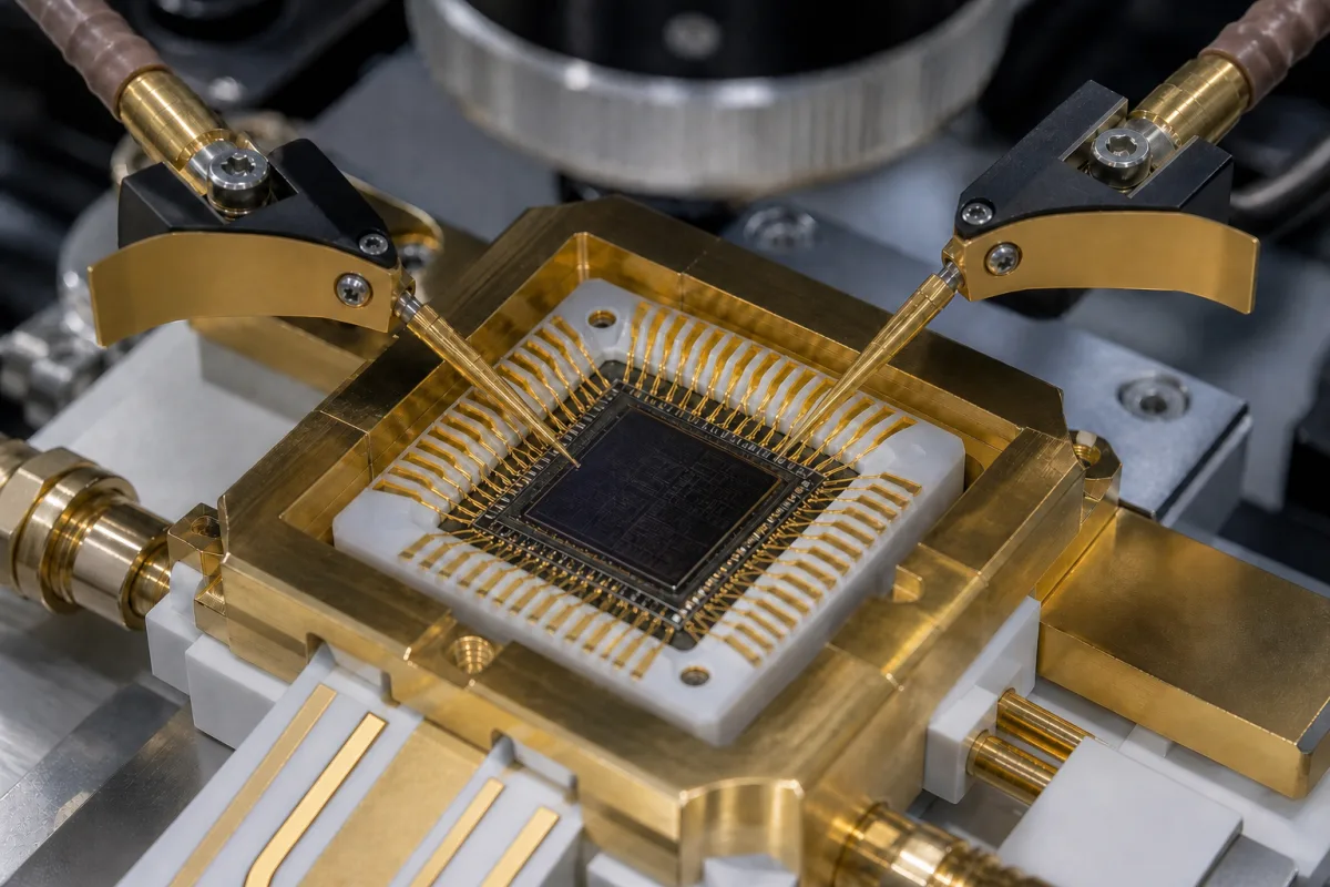
RF integrated circuits (RFICs) for wireless sensors, meters, alarms and IoT links · frequency bands, receive sensitivity, output power, current consumption, modulation and data rate, supply voltage, ESD, package, regulatory band rules
An RF integrated circuit (RFIC) processes radio signals on a chip — transceivers, front ends, amplifiers, mixers and synthesisers — inside wireless sensors, meters, alarms, remote controls and IoT nodes. Ask three things first: which frequency bands and modulation the link needs for your markets; the sensitivity, output power and current that set range and battery life; and the supply, temperature, ESD and package requirements of your board.
RF integrated circuits — sub-GHz and 2.4 GHz transceivers, receivers and transmitters, RF front ends, low-noise and power amplifiers, mixers and frequency synthesisers — as chips. Complete RF modules, antennas, discrete RF transistors, fibre-optic transceivers and baseband processors without radio are outside this page except where compared.
CNFX editorial research · Sources checked October 16, 2026 · 4 sources
Texas Instruments' CC1101 datasheet shows the figures that define a low-power RF transceiver IC. It targets the 315, 433, 868 and 915 MHz ISM/SRD bands and can be programmed across 300–348, 387–464 and 779–928 MHz; sensitivity is −116 dBm at 0.6 kBaud and 433 MHz and −112 dBm at 1.2 kBaud and 868 MHz at 1% packet error rate; output power is programmable up to +12 dBm on all supported frequencies; receive current is 14.7 mA at 1.2 kBaud and 868 MHz, sleep current 200 nA, and start-up from sleep to receive or transmit 240 µs. It supports 2-FSK, 4-FSK, GFSK, MSK, OOK and ASK at 0.6–600 kbps, includes a baseband modem with packet handling and 64-byte FIFOs controlled over SPI, and needs only a microcontroller and a few passive parts. Operating supply is 1.8–3.6 V and temperature −40 to 85 °C, with 750 V human-body-model ESD; the package is a 4 × 4 mm, 20-pin QLP. [1]
Editorial calculation: assuming the CC1101's +12 dBm output and −116 dBm sensitivity at the cited 433 MHz, 0.6 kBaud point can be used in the same link, and ignoring antenna gains, cable loss, propagation and fading margin, 12 − (−116) = 128 dB. The power-unit conversion gives 10^(12/10) ≈ 16 mW. This is an editorial arithmetic example, not manufacturer-published or measured operating range. [1]
A second maker's sub-GHz transceiver shows how figures differ between chips. Shenzhen Hope Microelectronics (HopeRF) has a page headed CMT2300AW whose descriptive text names CMT2300A. That text describes the device as an OOK and (G)FSK transceiver for 140–1,020 MHz (its specification table gives 127–1,020 MHz), with up to +20 dBm transmit power and −121 dBm sensitivity in the description (−120 dBm in the table), data rates of 0.5–300 kbps in FSK and 0.5–40 kbps in OOK, a 1.8–3.6 V supply, 8.5 mA receive current at −121 dBm sensitivity, 23 mA transmit current at 13 dBm output, and a 3 × 3 × 0.75 mm QFN package. [3] The page heading, description and table should be reconciled with HopeRF for the exact ordered variant and test conditions. [3]
HopeRF's description and specification table give different frequency and sensitivity figures above. Confirm the exact chip variant, band and test conditions before comparing link budgets or ordering; the page does not establish a matched test point for a cross-chip performance comparison. [3]
Give the supplier the frequency bands and countries, modulation and data rate, required sensitivity and output power, receive, transmit and sleep current budget, supply voltage, operating temperature, ESD level, package and size, interface to the host, need for integrated MCU or protocol stack, reference designs and certification support, and annual volume.
02
Check band rules for your markets
TI describes the CC1101 as suited to systems targeting EN 300 220 in Europe and FCC CFR Part 15 in the US. [1] In the US, 47 CFR 15.249 sets the field strength of intentional radiators in the 902–928 MHz, 2400–2483.5 MHz and 5725–5875 MHz bands at 50 mV/m for the fundamental and 500 µV/m for harmonics, and 250 mV/m in 24.0–24.25 GHz. [2] Section 15.249(c) specifies a measurement distance of 3 m for those field-strength limits. [2]
Editorial note: ask the supplier which radio rules its reference designs have been tested against, for which band and output power, and what test reports it can share for your certification.
03
RF chip datasheets, reference designs and lifecycle
When requesting quotations, ask each supplier for datasheet figures at your band and data rate, reference designs, lifecycle and longevity commitments, and certification support.
04
Compare long-range spread-spectrum transceivers on link budget
Semtech's product page for its SX1276/77/78/79 transceivers says its LoRa spread-spectrum modulation can reach sensitivity down to −148 dBm with a low-cost crystal and bill of materials, combined with an integrated +20 dBm power amplifier. The feature list gives a 168 dB maximum link budget, +20 dBm (100 mW) constant RF output versus supply voltage, a +14 dBm high-efficiency PA, programmable bit rate up to 300 kbps, IIP3 of −11 dBm, 9.9 mA receive current, 200 nA register retention, a 127 dB dynamic-range RSSI, a packet engine up to 256 bytes with CRC, FSK, GFSK, MSK, GMSK, LoRa and OOK modulation, and a QFN 28 package. [4]
Semtech publishes its maximum link-budget figure above. Its product page does not state the data-rate setting behind the −148 dBm sensitivity figure. Obtain sensitivity at the chosen modulation, bandwidth and data rate, and confirm permitted output power for the intended market before comparing with the other chips. [4]
2 companies list this product among what they make. Company figures are quoted from each
company's own website; every card states where the relationship came from.
Great Microwave Technology Co.,Ltd.
Manufacturing site to be confirmed for the order
Its website has a product page for rf integrated circuits.
Product scope checked 2026-10-12
Product page on own website · profile compiled by CNFX from public sources
Explore company information and manufacturing capabilities, then discuss the scope of your project with a relevant supplier.
Share this page
Compiled and source-reviewed by the CNFX editorial team.
Each manufacturer above links to the page on that company's own website where the product is listed, with the date we checked it. How we source and review
· Page last updated 13 October 2026
Buyer questions
What sensitivity do sub-GHz RF chips reach?
TI's CC1101 lists −116 dBm at 0.6 kBaud and 433 MHz at 1% packet error rate. [1]
How much power does an RF transceiver chip draw?
The CC1101 draws 14.7 mA receiving at 1.2 kBaud and 868 MHz and 200 nA in sleep. [1]
What field strength is allowed at 915 MHz in the US?
47 CFR 15.249(a) lists 50 mV/m for the fundamental in 902–928 MHz; paragraph (c) specifies a 3 m measurement distance. [2]
How do I compare sub-GHz transceiver chips?
Compare output power, sensitivity at the same data rate, and current: one chip gives +12 dBm and −116 dBm at 0.6 kBaud, another +20 dBm and −121 dBm with 8.5 mA receive current. [1][3]
What link budget can a LoRa transceiver IC reach?
Semtech lists a 168 dB maximum link budget for its SX1276/77/78/79, from sensitivity down to −148 dBm and +20 dBm output. [4]
Sources and what still needs a direct check
Sources checked 2026-10-16. The CC1101 datasheet is a Texas Instruments document used here as an example; 47 CFR 15.249 is a US regulation.