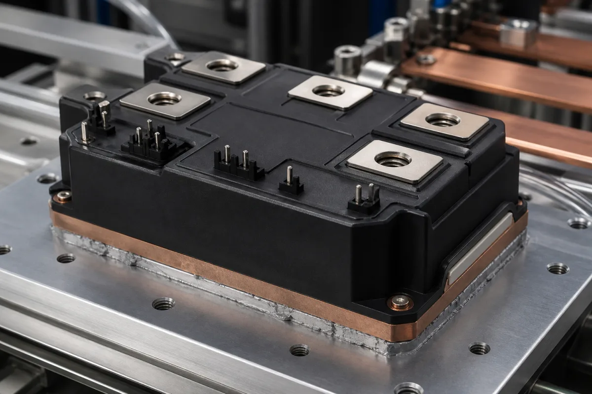
Silicon carbide switching · On-resistance instead of saturation voltage, gate voltage window, switching energy, isolation and baseplate
A silicon carbide (SiC) MOSFET power module packages SiC MOSFET dies — with or without separate SiC Schottky diodes — on an insulated substrate and baseplate in a half-bridge, full-bridge, six-pack or other configuration, for inverters, chargers and power supplies that switch faster or run hotter than silicon designs allow. Ask three things first: the blocking voltage and the on-resistance at your hottest junction temperature, the gate-voltage window and gate charge the driver must provide, and the switching energy, isolation and mechanical data for your converter.
Power modules built from silicon carbide MOSFETs, including SiC-MOSFET-only modules and modules with SiC Schottky diodes, in half-bridge, full-bridge, six-pack and single-switch configurations. Silicon IGBT modules (half-bridge, chopper, six-pack and PIM) are covered on the IGBT module page; discrete SiC MOSFETs, gate drivers, thyristor and diode modules and complete inverters are outside this page.
CNFX editorial research · Sources checked October 12, 2026 · 4 sources
Read on-resistance at the junction temperature you will reach
Wolfspeed's CAB760M12HM3 is a 1200 V, 62 mm-footprint half-bridge listed at 760 A with an RDS(on) of 1.33 mΩ at 25 °C. Its datasheet gives 1.33 mΩ typical and 1.73 mΩ maximum at 25 °C and 2.34 mΩ at a 175 °C virtual junction temperature (VGS = 15 V, ID = 760 A), a DC drain current of 1015 A at a 25 °C case and 765 A at 90 °C, a body-diode current of 515 A, a junction temperature range of −40 to 175 °C, and a junction-to-case thermal resistance of 0.068 °C/W typical (0.073 maximum). [1][2]
Editorial calculation: at 760 A the conduction loss per switch is I² × RDS(on) = 760² × 0.00133 Ω ≈ 768 W at 25 °C but 760² × 0.00234 Ω ≈ 1,352 W at 175 °C, about 1.76 times higher; with 0.068 °C/W junction-to-case, 1,352 W would raise the junction about 92 °C above the case, so design the thermal path with the hot on-resistance. [1]
Wolfspeed's module range spans blocking voltages of 650, 1200, 1700, 2300 and 3300 V in half-bridge, full-bridge, six-pack, single-switch, T-type and common-source configurations, from industry-standard 34 mm, 48 mm and 62 mm housings to 140 mm medium-voltage and 152 mm six-pack modules. [3] ROHM's BSM180D12P2C101 is a 1200 V, 204 A half bridge with 1360 W total power dissipation in a 122.0 × 45.6 mm package 17.5 mm thick, described as a SiC-MOSFET-only module with low body-diode Qrr and trr; ROHM marks it not recommended for new designs, so check lifecycle status before qualifying any module. [4]
Give the supplier the converter topology and configuration (half bridge, six-pack, other), DC-link voltage, RMS and peak current, switching frequency, maximum junction temperature you will allow, cooling method and heatsink, gate-driver voltage levels, isolation and creepage requirements, package footprint, qualification grade (industrial or automotive) and expected production life.
02
Set the gate-drive window and size the switching loss
The CAB760M12HM3 datasheet gives a maximum transient gate-source voltage of −8/+19 V and a recommended static operating level of −4/+15 V, with the turn-on gate voltage held at 15 V ±5%. Gate threshold is 1.8–3.6 V (2.5 V typical) at 25 °C and 2.0 V at 175 °C; total gate charge is 2724 nC and internal gate resistance 0.47 Ω. [1]
Measured at 600 V and 760 A with −4/+15 V drive and 1.0 Ω external gate resistors, turn-on energy is 20.3 mJ at 25 °C and 23.7 mJ at 175 °C, and turn-off energy 17.9 mJ at 25 °C and 17.8 mJ at 175 °C. [1] Editorial calculation: at 175 °C one switching cycle costs 23.7 + 17.8 = 41.5 mJ, so at 20 kHz and the same voltage and current the switching loss per switch would be 41.5 mJ × 20,000 ≈ 830 W; scale for your own current and voltage and confirm with the supplier's loss curves. [1]
Editorial calculation: driving 2724 nC between −4 V and +15 V at 20 kHz takes about 2724 nC × 19 V × 20,000 ≈ 1.04 W of gate-drive power per switch, a figure to pass to the gate-driver designer. [1]
03
Check isolation, creepage and mounting of the package
Wolfspeed lists a case isolation voltage of 4 kV AC (50 Hz, 1 minute), a comparative tracking index of 600, terminal-to-baseplate clearance of 12.70 mm and creepage of 15.30 mm, stray inductance of 4.9 nH between terminals 1 and 3, a weight of 179 g, a lightweight AlSiC baseplate mounted with M6 bolts and power terminals on M4 bolts, and a 110 × 65 × 12.2 mm module size for the CAB760M12HM3. [1][2]
Editorial note: the IGBT-module habit of reading collector-emitter saturation voltage does not carry over — a SiC MOSFET's conduction drop is current × RDS(on), so the field below is filled from on-resistance, and the body-diode or Schottky-diode data replace a separate freewheeling-diode rating.
04
Module values to compare across SiC suppliers
Each row names the condition the value was measured at; compare modules only at matching voltage, current and temperature.
Field
Published values and meaning
Ask the supplier for
Rated voltage (V)
CAB760M12HM3 and BSM180D12P2C101: 1200 V; family to 3300 V. [1][4][3]
Blocking voltage and derating.
Rated current (A)
CAB760: 760 A listed, 765 A DC at 90 °C case; BSM180: 204 A. [2][1][4]
Current at your case temperature.
Switching frequency (kHz)
Set by loss budget; CAB760 Eon/Eoff 23.7/17.8 mJ at 175 °C. [1]
Loss curves versus current.
Collector-emitter saturation voltage (V)
Not used for SiC MOSFETs; read RDS(on): 1.33 mΩ at 25 °C, 2.34 mΩ at 175 °C. [1]
Explore company information and manufacturing capabilities, then discuss the scope of your project with a relevant supplier.
Share this page
Compiled and source-reviewed by the CNFX editorial team.
Each manufacturer above links to the page on that company's own website where the product is listed, with the date we checked it. How we source and review
· Page last updated 13 October 2026
Buyer questions
Why does SiC module on-resistance matter more than at room temperature?
Wolfspeed's CAB760M12HM3 rises from 1.33 mΩ at 25 °C to 2.34 mΩ at 175 °C, so conduction loss at 760 A grows about 1.76 times. [1]
What gate voltage does a SiC MOSFET module need?
Wolfspeed recommends −4/+15 V static for the CAB760M12HM3, with −8/+19 V as the transient maximum. [1]
Do SiC modules include a separate diode?
Some are SiC-MOSFET-only and rely on the body diode; ROHM describes the BSM180D12P2C101 that way, with low body-diode Qrr and trr. [4]
Sources and what still needs a direct check
Sources checked 2026-10-12. Wolfspeed and ROHM are SiC device makers describing their own power modules: Wolfspeed's module family page, its CAB760M12HM3 product page and datasheet, and ROHM's BSM180D12P2C101 product page.