Editorial Technical Reference

Power Electronics Board

This page explains how Power Electronics Board is classified within Computer, Electronic and Optical Product Manufacturing. Technical values and manufacturer relationships are research references; confirm the current specification and supplier evidence for each order.

Technical Definition & Core Assembly

A printed circuit board assembly that manages and controls electrical power conversion, distribution, and regulation within an industrial system.

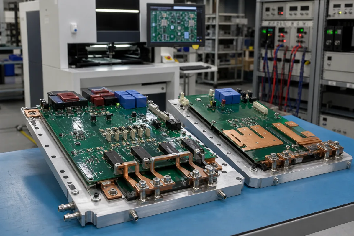
Representative product image. Confirm appearance and specifications with the manufacturer.

Product Specifications

Technical details and manufacturing context for Power Electronics Board

Definition
The Power Electronics Board is a critical control component within Industrial Systems that serves as the central interface for power management functions. It receives input power from the system's main supply, processes it through various semiconductor devices and control circuits, and delivers precisely regulated output power to different subsystems and actuators. This board enables efficient energy conversion, protects against electrical faults, and ensures stable operation of motors, sensors, and other electronic components throughout the industrial environment. The board is designed for use in computer, electronic, and optical product manufacturing, and is classified as a component-level device. It is typically mounted within an industrial enclosure and interfaces with the main power supply, control systems, and load devices. The board's construction includes FR-4 epoxy laminate, copper traces, and semiconductor devices such as IGBTs or MOSFETs. Key parameters include an input voltage range of 85–264 V AC, output power from 500 to 2000 W, output voltage accuracy of ±1%, and a switching frequency of 50–200 kHz. It operates over a temperature range of -40 to 85 °C and can be stored from -55 to 125 °C. The board is rated for relative humidity of 5–95% non-condensing, and offers ingress protection from IP54 to IP65. Board thickness ranges from 1.6 to 3.2 mm, with copper weight of 2–4 oz. Isolation voltage is 1500–4000 V DC, and EMC compliance is to EN 55032 Class A. These specifications are reference ranges and must be verified for the specific model and application with the legal manufacturer or supplier. The board is not a standalone product but a component that requires integration into a larger system. It is essential to confirm compatibility with the system's power requirements, mechanical mounting, and environmental conditions before procurement.
Working Principle
The Power Electronics Board operates by receiving alternating current (AC) or direct current (DC) input power from the industrial system's main supply. This power flows through input filtering circuits that remove electrical noise and transients. Semiconductor switching devices (such as IGBTs, MOSFETs, or thyristors) controlled by microcontroller or DSP-based circuits then rapidly switch the power on and off at high frequencies. This switching action, combined with energy storage components (inductors and capacitors), enables power conversion between different voltage and current levels. Feedback circuits continuously monitor output parameters and adjust switching patterns to maintain precise regulation. The processed power is then distributed through output terminals to various industrial system components.
Common Materials
FR-4 Epoxy Laminate, Copper Traces, Semiconductor Devices (IGBTs/MOSFETs)
Technical Parameters
ParameterTypical rangeNotes & selection driver
Input Voltage Range85–264 V ACUniversal input for global useIEC 61000-4-30
Output Power500–2000 WDepends on application
Output Voltage Accuracy±1 %Regulation over line and load
Switching Frequency50–200 kHzHigher frequency reduces size
Operating Temperature-40–85 °CExtended range for industrial
Storage Temperature-55–125 °CNon-operating
Relative Humidity5–95 % RHNon-condensingIEC 60068-2-78
Ingress ProtectionIP54–IP65Dust and water resistanceIEC 60529
Board Thickness1.6–3.2 mmStandard thickness for powerIPC-6012
Copper Weight2–4 ozHigh current carrying capacityIPC-6012
Isolation Voltage1500–4000 V DCReinforced insulationIEC 60950-1
EMC ComplianceEN 55032 Class AIndustrial environmentEN 55032

Ranges are indicative industry figures for RFQ preparation, not a supplier commitment. Confirm every value and standard with the legal manufacturer before ordering.

Components / BOM
  • Power Semiconductor Module
    Performs high-current switching operations for power conversion
    Material: Silicon or Silicon Carbide semiconductor with copper terminals
  • Gate Driver Circuit
    Provides proper voltage and current signals to control power semiconductor switches
    Material: Integrated circuits with discrete transistors and resistors
  • DC-Link Capacitors Part
    Stores and filters intermediate DC power, smoothing voltage ripples
    Material: Aluminum electrolytic or film capacitors
  • Current Sensors
    Monitors output current for protection and control feedback
    Material: Hall-effect sensors or shunt resistors with amplification circuits
  • Heat Sink Part
    Dissipates heat generated by power semiconductor devices
    Material: Aluminum alloy with thermal interface material
  • Input Filter
    Strips noise and transients off the incoming supply before the switching stage.
  • Control Microcontroller / DSP
    Runs the switching pattern and closes the loop on the feedback readings.
  • Printed Circuit Board
    The board itself: substrate and heavy copper carrying the power and gate signals.

Industry Taxonomies & Aliases

Commonly used trade names and technical identifiers for Power Electronics Board.

Applied To / Applications

This component is essential for the following industrial systems and equipment:

Industrial Ecosystem & Supply Chain Structure

Complementary Systems
Downstream Applications
Specialized Tooling

Application Fit & Sizing Matrix

Operational Limits
pressure: Standard atmospheric pressure (no pressure-sensitive components)
other spec: Humidity: 5-95% non-condensing, Vibration: 5g max, IP rating: IP20 (indoor use only)
temperature: -40°C to +85°C operating, -55°C to +125°C storage
Media Compatibility
✓ Clean air environments ✓ Industrial control cabinets ✓ Dry manufacturing facilities
Unsuitable: High-moisture or corrosive chemical atmospheres (e.g., marine, chemical processing plants)
Sizing Data Required
  • Input voltage range (V)
  • Maximum output power requirement (W)
  • Required control interface type (e.g., analog, digital, CAN bus)

Reliability & Engineering Risk Analysis

Failure Mode & Root Cause
Thermal stress failure
Cause: Inadequate heat dissipation leading to overheating of components like IGBTs, MOSFETs, or capacitors, often due to dust accumulation, fan failure, or poor thermal interface material degradation.
Electrolytic capacitor degradation
Cause: Electrolyte evaporation or leakage from prolonged exposure to high temperatures, voltage stress, or ripple currents, resulting in reduced capacitance, increased ESR, and eventual short/open circuit.
Maintenance Indicators
  • Audible high-pitched whining or buzzing from capacitors or transformers indicating imminent failure
  • Visible bulging or leaking of electrolytic capacitors, or discoloration/burning on PCB traces or components
Engineering Tips
  • Implement regular thermal imaging inspections to identify hot spots and ensure cooling systems (fans, heatsinks) are clean and functional
  • Use conformal coating on the PCB to protect against moisture, dust, and contaminants, and replace electrolytic capacitors with solid polymer or ceramic types in critical locations for higher reliability

Indicative industry ranges for design and RFQ preparation. Confirm the exact figures and applicable standard with the manufacturer before specifying.

Compliance & Manufacturing Standards

Applicable Standards
IEC 61000-6-2 Electromagnetic Compatibility (EMC) UL 60950-1 Safety of Information Technology Equipment

Quoted from the published standard.

Manufacturing Precision
  • Component Placement: +/-0.1mm
  • PCB Warpage: 0.75% of diagonal length
Quality Inspection
  • In-Circuit Test (ICT)
  • Thermal Cycling Test (-40°C to +125°C)

Manufacturers of Power Electronics Board

1 company lists this product among what they make. Company figures are quoted from each company's own website; every card states where the relationship came from.

Tortai Technologies Co., Ltd.
Dongguan, Guangdong, CN
Listed on the company's own website · profile compiled by CNFX from public sources

Manufacturer listings support early research and capability understanding. They are not certification, ranking, or transaction guarantees.

Technical documentation
Request current drawings, revision history, and a signed specification sheet.
Manufacturing capability
Verify equipment lists, process limits, capacity, and representative production evidence.
Inspection readiness
Confirm test methods, calibrated equipment, sampling plans, and traceable reports.
Supplier transparency
Check the legal entity, factory address, ownership, certifications, and direct contacts.

CNFX does not score or rank suppliers. Buyers must verify all claims and documents with the legal manufacturer before ordering.

Supply Chain Commonly Integrated Components

Wireless Radio Module

A hardware component that enables wireless communication by transmitting and receiving radio frequency signals.

Explore Specs →
Vision Alignment System

A computer vision-based subsystem that ensures precise alignment of components during automated chassis assembly.

Explore Specs →
Ethernet Magnetics

Passive electronic component that provides electrical isolation, signal conditioning, and EMI filtering for Ethernet interfaces

Explore Specs →
Industrial Touchscreen Display

A ruggedized touchscreen interface component designed for industrial environments, providing visual output and user input capabilities.

Explore Specs →

Frequently Asked Questions

What is the typical input voltage range for this board?

The board is designed for a universal input voltage range of 85–264 V AC, as listed in the parameters. This range is intended for global use, but you must verify the exact range for your specific model with the manufacturer.

What output power can this board provide?

The output power is specified as 500–2000 W, depending on the application. This is a reference range; the actual output power capability depends on the specific configuration and must be confirmed with the supplier.

What are the operating temperature limits?

The board operates over a temperature range of -40 to 85 °C, with a storage range of -55 to 125 °C. These are industrial extended ranges, but you should verify that your application's environment falls within these limits.

What standards are referenced for this board?

The board references several standards for verification, including IEC 61000-4-30 for input voltage, IEC 60068-2-1/2 for temperature, IEC 60068-2-78 for humidity, IEC 60529 for ingress protection, IPC-6012 for board thickness and copper weight, IEC 60950-1 for isolation voltage, and EN 55032 for EMC compliance. These are procurement references and do not guarantee certification; always confirm compliance with the manufacturer.

Data Basis

Editorial classification, named public sources where available, and source-reviewed manufacturer records.

Preliminary Technical Classification
This page supports structured research, RFQ preparation, and supplier evaluation. It does not replace buyer-led supplier qualification, standards review, or technical approval.
Buyer enquiry

Request manufacturing insight for Power Electronics Board

Ask for use case, specification boundaries, supplier type, and RFQ preparation information for this product.

Where it goes
Straight to the CNFX editorial desk, and to the manufacturer if this product is linked to a claimed profile. Nothing is broadcast to a supplier list.
Your details stay here
We do not sell or rent enquiry data, and we do not add you to a mailing list. Used only to answer this request.
No commission, no middleman
CNFX is a directory. We take no cut of any order and never negotiate on a supplier's behalf.
What we don't claim
A listing is not an endorsement. Qualify every supplier and verify every figure yourself before ordering.

Your business information is used only to process this request.

Thank you! Your message has been sent. We'll respond within 1–3 business days.
Sorry, we couldn't send your message. Please try again, or email us at contact@cnfx.com.

Need to Manufacture Power Electronics Board?

Compare manufacturer profiles with relevant product and process capability.

Previous Product
XY Positioning Stage
Last Product
Get QuotesChat