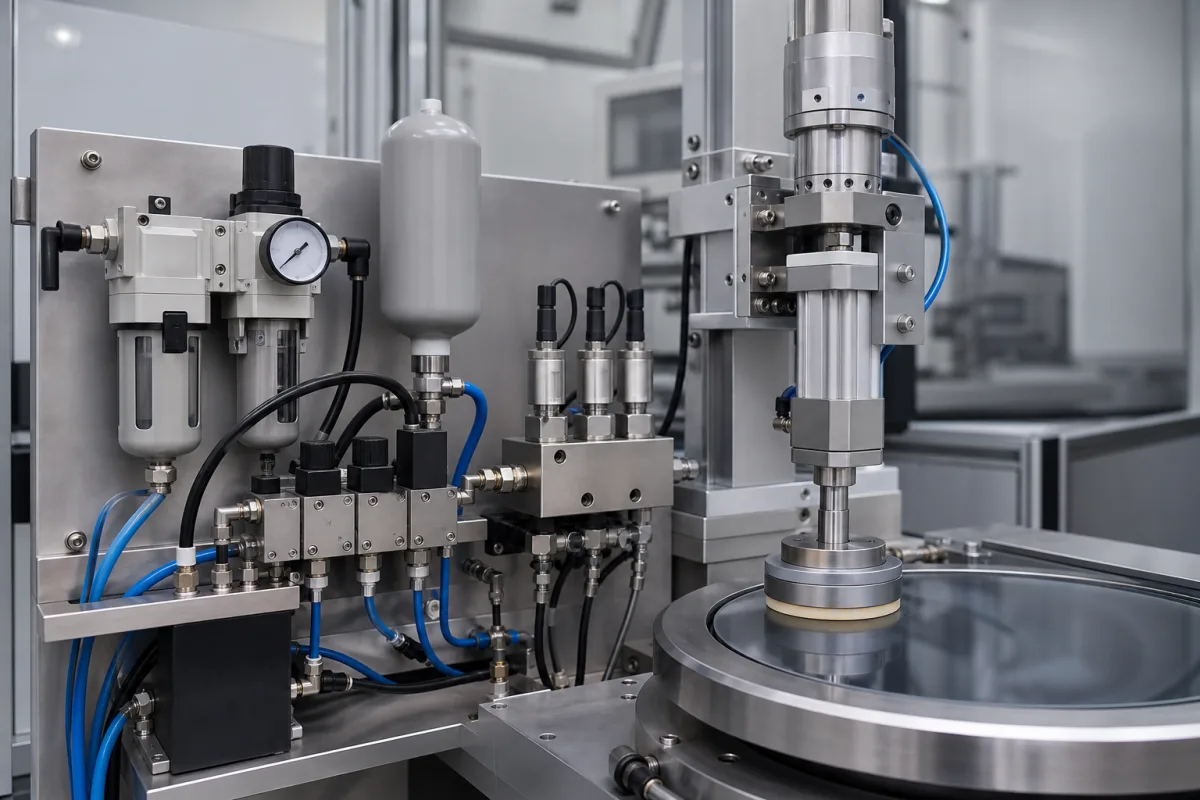
Polishing-pressure control mechanism for optical lens polishing: the pneumatic loading loop, contact-force feedback and multi-zone tool pressure
The sub-assembly that sets how hard the tool presses on the lens · cylinder, electro-pneumatic regulator, pressure sensor and valves in one loop, a 2 N contact force held between 1.99 and 2.09 N by force feedback, and an ophthalmic lapping head that splits 18 pneumatic plungers into seven pressure zones
In optical polishing, removal at each point follows the Preston relation: depth removed per unit time is proportional to contact pressure times relative speed. The spindle sets the speed; the pressure has to come from a separate mechanism that loads the tool against the lens, keeps that load steady as the tool sweeps across a curved surface, and in some heads varies it from zone to zone. That mechanism is a sub-assembly of the polishing machine with its own sensors, valves and control loop.
Pressure and force control mechanisms built into optical lens and mirror polishing machines: pneumatic cylinders or bellows with electro-pneumatic and precision regulators, pressure sensors and solenoid valves, force-sensor feedback loops, pneumatic counterweights for heavy tools, and multi-zone pneumatic tool heads. Complete lens polishing machines, with spindle speeds, machine types and diameter ranges, are covered on the Precision optical lens polishing machine page; stand-alone compressed-gas and electro-pneumatic pressure regulators, read by their flow curves, on the Pressure regulator page.
CNFX editorial research · Sources checked October 12, 2026 · 6 sources
From the air supply to the tool: cylinder, electro-pneumatic regulator, pressure sensor and three-stage regulator in one closed loop
Fine Ace Technology's patent US 6,910,946 B2 describes a polishing machine whose tool head is pressed onto the workpiece by an air cylinder, with the pressure held constant by the circuit below; the patent's stated aim is polishing at a constant pressure, which earlier machines lacked a means to maintain. [1]
Peter Wolters AG's patent US 4,742,651 for lapping, honing and polishing machines starts from a different problem: a heavy tool whose own weight exceeds the processing pressure needed. A pneumatic adjusting member counteracts the tool's weight, and a program control vents it through adjustable throttles so that pressure builds up in time steps to the rated value, compared all the while with a thrust sensor's reading. The patent prefers pneumatic over hydraulic adjustment because hydraulic drives are stiff and their friction and hysteresis make each pressure build-up hard to reproduce, and it uses a travel indicator to slow the tool just before it touches down. [2]
Element in the patent
Where it sits
What it does
Air unit (filter, regulator, lubricator)
After a solenoid valve on the compressed-air source [1]
Switch the supply and the direction of air into the cylinder [1]
Ask whether the mechanism controls pressure in the cylinder or measured force at the tool, how a heavy tool's own weight is offset, and how the pressure ramp at touchdown is set.
02
Holding 2 N on a bonnet tool: force feedback, response time and spread
Li, Cheung, Lam and Lun at the Hong Kong Polytechnic University closed the loop on force rather than air pressure: a single-axis force sensor between the workpiece fixture and a parallel mechanism on a bonnet polishing machine, with impedance control plus a high-frequency robust control law adjusting the Z position. Static results at a 2 N target: [4]
The authors chose deliberately soft control parameters, because moving the mechanism too fast during polishing causes vibration that marks the surface, and found that the force loop had to run at a markedly lower bandwidth than the position loop. They also cite a piezo-stage system for micro-optics holding 0 to 200 mN with a 1 ms response and 5 nm position resolution. [4]
Shi and colleagues show why force, not tool position, is the controlled quantity: contact deformation between tool, abrasive and an aspheric part shifts the tool normal to the surface and changes the polishing force sharply. Compensating that displacement through force control cut roughness on their aluminium ellipsoid parts from 0.4 µm to 0.21 µm and the unevenness of roughness across the surface from 112.5 % to 19 %. [5]
At the other end of the scale, Ding and Yao polished a Wolter-I X-ray mirror with a φ20 mm polyurethane head pressed on at 0.5 N, and describe removal with the Preston equation dz/dt = k·v·p. [6] Editorial calculation: 0.5 N on a full 20 mm circle is about 1.6 kPa of mean contact pressure.
State the force or pressure range, the resolution and steadiness required at the lowest setting, and the response time acceptable when the tool crosses a change of curvature.
03
Different pressures across one tool: 18 pneumatic plungers and seven zones in an ophthalmic lapping head
Micro Optics Design Corporation's patent US 6,110,017 shapes the flexible membrane of an ophthalmic lapping head with an array of pneumatic cylinders: twelve outer and six inner plungers in two concentric circles around a central stem, together defining seven regions that can be grouped into four sectors. [3]
Each cylinder line has a solenoid-operated valve on an air manifold, and a single computer-controlled, fast-response precision proportional pressure regulator on the manifold supply sets them one at a time: one valve opens, the regulator changes its setting, and the patent says all six lines are closed and pressurised within a few seconds. The membrane can be shaped from about −6 dioptres to flat and to about +16 dioptres, matching the base and cross curves of the lens, and is undulated so that slurry reaches the centre of the lens instead of being depleted there. [3]
Editorial note: this sequential scheme trades regulator count for setting time; a head that has to change zone pressures during a stroke would need a regulator per zone, which is a question to put to the maker.
For multi-zone heads, ask how many independent pressures there are, how they are set and how fast a new pressure pattern is established.
04
What to send when specifying a polishing pressure control mechanism
Paste it into your enquiry below or into an email to a maker, then replace every bracket.
Machine: [polishing machine type; tool type and diameter; tool weight]
Workpiece: [lens or mirror diameter; radius range; asphere or freeform]
Control variable: [cylinder pressure or measured contact force]
Range and steadiness: [force or pressure range; resolution; allowed spread at lowest setting]
Dynamics: [ramp at touchdown; response time; vibration limits]
Zones: [single pressure or number of zones; how set]
Air: [supply pressure; filtration; regulator and sensor interfaces]
Explore company information and manufacturing capabilities, then discuss the scope of your project with a relevant supplier.
Share this page
Compiled and source-reviewed by the CNFX editorial team.
Each manufacturer above links to the page on that company's own website where the product is listed, with the date we checked it. How we source and review
· Page last updated 13 October 2026
Buyer questions
How is polishing pressure kept constant in a pneumatic polishing head?
In Fine Ace's patent, a pressure sensor on the cylinder line reports to a controller that corrects an electro-pneumatic regulator whenever pressure departs from the set value, with a three-stage precision regulator on the other port. [1]
How steady can closed-loop contact force be?
In PolyU's bonnet-polishing tests at a 2 N target, force stayed between 1.99 and 2.09 N, with a 5.4 s response time. [4]
Why control force rather than tool position?
Contact deformation shifts the tool and changes force sharply; force-based compensation cut roughness from 0.4 to 0.21 µm in one aspheric polishing study. [5]
Why use pneumatics rather than hydraulics to load a lapping tool?
Peter Wolters' patent says hydraulic drives are stiff and their friction and hysteresis make the pressure build-up hard to reproduce; pneumatic adjustment is almost friction-free. [2]
Sources and what still needs a direct check
Sources checked 2026-10-12. Loop architectures come from patents by Fine Ace Technology, Peter Wolters and Micro Optics Design; force-control results from studies at the Hong Kong Polytechnic University and Jiaxing Vocational Technical College; the low-force mirror case and Preston relation from a PLOS One study of Wolter-I mirror polishing.