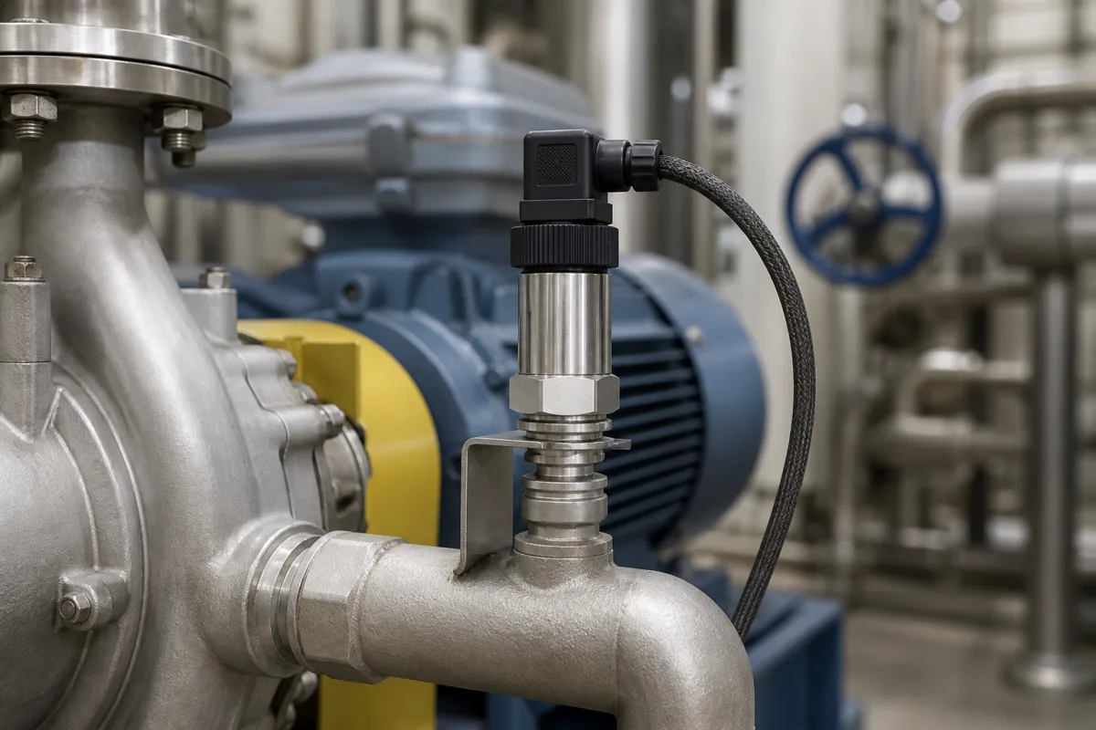
Pump pressure sensors: suction and discharge transmitters that measure pump head, guard the inlet and survive the pressure peaks of pump starts and stops
Sensors on the suction and discharge of a pump · where they go, how two readings become pump head, why the suction side may need a range below atmospheric, and the pressure peaks from pump starts and stops
A pump's pressure sensors sit close to the suction and discharge flanges, where the readings describe the pump itself, but also where the inlet may fall below atmospheric pressure and where starts, stops and valve closures send pressure peaks through the pipe. The pair of readings gives the pump's head and, from the suction side, the margin against the liquid's vapour pressure. Picking the sensor is a matter of range on each side, accuracy where it counts in metres of head, response time and protection against peaks.
Electronic pressure sensors and transmitters fitted to the suction and discharge of pumps and pump sets for head measurement, inlet and dry-run protection and pressure control, including differential transmitters across the pump. General-purpose industrial pressure transmitters, their accuracy terms, overload ratings and output loops are covered on the Industrial pressure sensors and transmitters page; sensing elements on the Pressure transducer sensing element page; differential-pressure monitoring of dust collector filters on the Pressure monitoring system page; mechanical pressure gauges and pressure switches on their own pages.
CNFX editorial research · Sources checked October 13, 2026 · 3 sources
Sensors at the suction and discharge flanges: pump head from two pressure readings, and a suction range that goes below zero
Jacques Chaurette's pump field-measurement guide puts the two sensors as close as possible to the suction and discharge flanges, close enough that there is no appreciable friction loss or velocity change between the gauge and the flange. Total head is then the difference of the two readings converted to head (in feet of fluid, 2.31 × pressure in psi ÷ specific gravity), corrected for the height of each gauge and the difference in velocity head between discharge and suction. [1]
Editorial calculation with example values: a pump on water (SG 1.0) reading −3 psig at the suction and 57 psig at the discharge has Δp = 60 psi, so 2.31 × 60 ≈ 139 ft (about 42 m) before the gauge-height and velocity-head corrections. [1] The guide warns that the pressure at the pump inlet may be negative, so the suction instrument may need to read below atmospheric; it also derives NPSH available from the suction reading by adding barometric head and subtracting the liquid's vapour pressure head. [1] Grundfos's RPI relative pressure transmitters, sold as a system solution with Grundfos pumps, are ranged from zero upward (0–0.6 bar to 0–25 bar), so a suction position that can go below atmospheric needs a range checked against that case. [2]
With a single discharge sensor, the guide shows how suction head can be calculated from the static level and the friction and equipment losses on the inlet side instead of measured, and notes that when the suction line is large, short and has a fully open low-restriction valve, the inlet pressure head can be taken as the static head. [1] Grundfos also offers a differential pressure transmitter (DPI) with a capillary tube to its second port, so one instrument reads the difference between two points. [2]
4–20 mA from 12–30 V DC; RPI+T 2 × 0–10 V from 16.6–30 V DC [2]
Sensor and wetted parts
Silicon MEMS chip with corrosion-resistant coating, AISI 316 L, EPDM or FKM; IP67 [2]
Ambient air temperature
Stated as −13 to 140 °F and as −25 to 95 °C on the same sheet (the 0–0.6 bar sheet gives −25 to 60 °C) [2]
Editorial calculation: ±2 % FS on a 0–10 bar sensor is ±0.2 bar, about ±2 m of water head, and two such sensors used for a suction-to-discharge difference can be out by up to ±0.4 bar in the worst case. [2] The Grundfos 0–10 bar sheet gives two different ambient limits (140 °F is 60 °C, not 95 °C); confirm the ambient rating with Grundfos before mounting the sensor in a hot pump room.
02
Pump starts, stops and fast valve closure: pressure peaks, a pulse snubber and overload at three times the range
Danfoss's data sheet for its DST P600/P650 heavy-duty transmitters explains why the P650 has an integrated pulse snubber: cavitation, liquid hammer and pressure peaks may occur in liquid-filled systems when flow velocity changes, for example with fast valve closing or pump starts and stops, and the problem may occur on the inlet and outlet side even at rather low operating pressures. Danfoss states that media viscosity has only little effect on the response time with the snubber fitted, which does not exceed 4 ms up to 100 cSt. [3]
Editorial calculation: Danfoss's overload ratings are three times nominal (120/40 up to 1,500/500), and Grundfos's 60 bar system burst pressure is six times a 0–10 bar range. [3][2] The two makers' response times also differ by a factor of 25 (2 ms against 50 ms (typ.)), Editorial note: a sensor with the shorter response time will follow faster pressure changes; whether that is wanted depends on whether the reading feeds a protection trip or a speed controller. [3][2] Danfoss notes that the burst pressure reached can fall depending on the pressure connection, mounting torque and counterpart material. [3]
Tell the supplier the pump type and its number of starts per hour, the fastest valve closure in the line, the maximum pressure including transients, and whether the signal is used for protection or control; ask whether a snubber or a damped version is available and what it does to response time.
03
From sensor to pump controller: 4–20 mA loop load, ratiometric outputs and a temperature signal in the same body
Grundfos's RPI with 4–20 mA output allows a load of up to 60 Ω at 12.5 V DC supply, 100 Ω at 13.3 V and 900 Ω at 30 V, draws 660 mW and is limited to 30 m of signal cable; the RPI+T version gives separate 0–10 V pressure and temperature signals sharing one ground terminal, with a minimum load of 10 kΩ. [2] Danfoss's DST P600 range offers 0–10 V, 1–5 V, 1–6 V, 4–20 mA and 10–90 % ratiometric (5 V ± 0.5 V supply) outputs with output clipping at minimum and maximum. [3]
Editorial note: at the low end of the Grundfos supply range the permissible 4–20 mA loop load is small (60 Ω at 12.5 V), so a pump controller input resistance and cable resistance have to be added up before choosing a 12 V supply. [2] Grundfos lists its transmitters for water treatment and distribution, light chemical industry, HVAC, heat pumps, cooling towers and solar systems, with potable-water approvals (WRAS, KTW, ACS, NSF 61), which matters when the sensor is wetted by drinking water in a booster set. [2]
State the controller input (4–20 mA with its load resistance, 0–10 V, ratiometric), supply voltage, cable length, connector (M12, DIN, Packard, Deutsch), wetted materials and any drinking-water approvals required.
04
What to state for a pump pressure sensor
Paste it into your enquiry below or into an email to a maker, then replace every bracket.
Position: [suction; discharge; across the pump]
Range: [including below atmospheric on suction; maximum including transients]
Accuracy: [% FS over the working temperature; head tolerance in m]
Dynamics: [response time; snubber or damping; start/stop frequency]
Medium: [liquid; temperature; viscosity; particles; potable water approvals]
Signal: [4–20 mA, 0–10 V or ratiometric; supply; loop load; cable length]
Connection: [process thread; connector; IP rating]
Explore company information and manufacturing capabilities, then discuss the scope of your project with a relevant supplier.
Share this page
Compiled and source-reviewed by the CNFX editorial team.
Each manufacturer above links to the page on that company's own website where the product is listed, with the date we checked it. How we source and review
· Page last updated 13 October 2026
Buyer questions
How do you calculate pump head from suction and discharge pressure?
Take the difference of the two readings and convert it to head: 2.31 × Δp (psi) ÷ specific gravity gives feet of fluid, then correct for gauge heights and the velocity head difference. [1]
Can the suction pressure of a pump be negative?
Yes; the field-measurement guide warns that inlet pressure may be negative, so the suction instrument may need to read below atmospheric. [1]
Why do pump pressure sensors need a pulse snubber?
Danfoss explains that pump starts and stops and fast valve closure cause cavitation, liquid hammer and pressure peaks on both sides of a pump; its DST P650 has an integrated snubber and still responds within 4 ms up to 100 cSt. [3]
How accurate is a pump pressure transmitter?
Published examples are ±2 % FS from 0 to 80 °C for Grundfos's RPI and ±0.5 % FS accuracy with a ≤ ±2 % FS total error band from −20 to 100 °C for Danfoss's DST P600. [2][3]
Sources and what still needs a direct check
Sources checked 2026-10-13. Three sources from three publishers: Grundfos's product guide for its Direct Sensor pressure transmitters (RPI and DPI), Danfoss's data sheet for DST P600, P607 and P650 heavy-duty transmitters (2023), and the field-measurement chapter of Jacques Chaurette's pump fundamentals guide (pumpfundamentals.com).