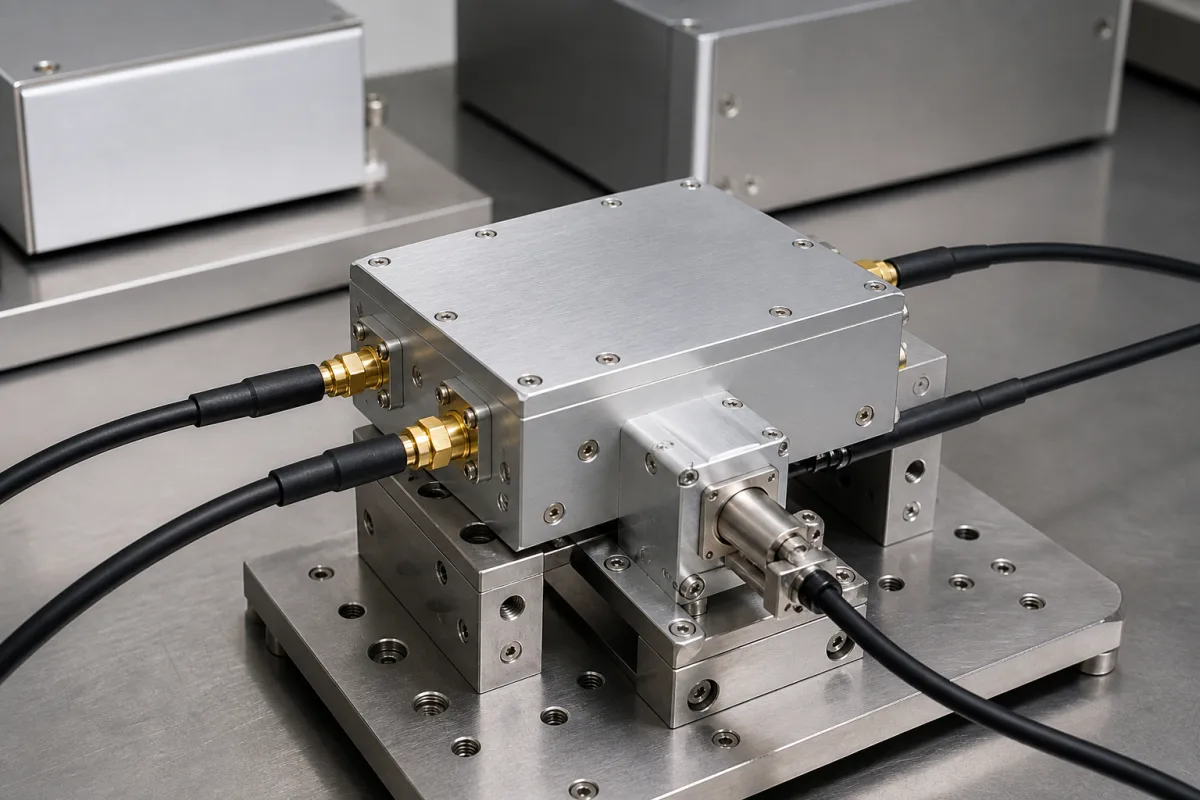
RF switches that route signals between paths in transceivers, test systems and switch matrices · Frequency range, insertion loss, isolation, return loss or VSWR, switching time, power handling and compression, control logic and supply, temperature, package or connectors
An RF switch connects a COM port to one of two or more RF paths under a control signal; it is used for band and antenna selection, transmit/receive switching, bypass paths and automated test networks. Loss and isolation change with frequency, so the data sheet must be read across the whole band. Ask three things first: what band and power the switch must carry, how much loss and how much isolation the path can tolerate at the highest frequency, and how fast and with what logic it must switch.
Solid-state RF switches supplied as surface-mount components or connectorised modules, including SPDT and multi-throw types with integral drivers. Electromechanical coaxial relays, waveguide switches and complete switch-matrix systems are outside this page except where compared.
CNFX editorial research · Sources checked October 11, 2026 · 4 sources
Read insertion loss, isolation and return loss across the band
Mini-Circuits' HSWA2-30DR+ data sheet describes a 50 ohm absorptive SPDT switch for DC to 3000 MHz with an internal CMOS driver, in a 4 × 4 mm package 0.9 mm high. Its insertion loss is 0.75 dB (typ.; 1.0 dB max) at 1000 MHz, 0.95 dB (typ.; 1.2 max) at 2000 MHz and 1.2 dB (typ.; 1.4 max) at 3000 MHz; isolation between the COM port and RF1/RF2 is 64, 50 and 44 dB (typ.; 55, 46 and 40 dB min) at those frequencies, and return loss at the COM port is 20, 17 and 14 dB (typ.). Its lowest frequency is set by the coupling capacitors at the RF ports. [1]
The ZASWA-2-50DR+ data sheet describes a connectorised 50 ohm absorptive SPDT switch for DC to 5000 MHz with an integral TTL driver and SMA connectors. Its insertion loss is 1.3, 1.7, 1.8 and 3.0 dB (typ.; 2.0, 2.5, 3.0 and 4.5 dB max) in the DC–100, 100–1000, 1000–2000 and 2000–5000 MHz bands, its in-out isolation is 100, 90, 82 and 68 dB (typ.; 80, 75, 65 and 46 dB min) in the same bands, and VSWR is 1.3:1 (typ.). [2]
Editorial calculation: in that connectorised switch, isolation (typ.) falls by 32 dB from the lowest band to the highest (100 − 68), and the guaranteed minimum falls by 34 dB (80 − 46), so set isolation limits at your highest operating frequency. [2]
A reflective switch built for handsets shows the other end of the range. Skyworks lists its SKY13453-385LF as a single-control SPDT (SP2T) reflective switch for 0.01 to 6 GHz, intended for mode switching ahead of a power amplifier in cellular or WLAN equipment, with insertion loss of 0.4–0.7 dB (typ.), isolation of 27 to 15 dB (typ.) across the band (0.40 dB and more than 25 dB at 2.0 GHz), IIP3 of 57 dBm (typ.) and a 1 dB compression point (IP1dB) of 33 dBm (typ.), in a 6-pin QFN of 1 × 1 × 0.45 mm rated MSL1 at 260 °C to JEDEC J-STD-020; the page shows it in production and names SKYA21024 as its replacement part. [4]
Editorial calculation: 15 dB of isolation at the top of that band against 44 dB (typ.) for the absorptive HSWA2-30DR+ at 3,000 MHz is a 29 dB gap, about 10^2.9 ≈ 800 times more leaked power on the off path; a reflective switch also leaves the off port unterminated, so check whether your source or amplifier tolerates the reflection. [4][1]
Give the supplier the frequency range, number of throws, absorptive or reflective requirement, insertion loss and isolation limits at your highest frequency, return loss or VSWR, switching time, RF input power and compression or IP3 requirement, control logic levels, supply voltages and current budget, temperature range, and surface-mount package or connector type.
02
Check switching time, power handling, control and supply
For the HSWA2-30DR+, Mini-Circuits lists switching time of 2.0 µs, input 1 dB compression of +31 dBm (typ.; +29 min) and input IP3 of +55 dBm (typ.) at 10–1000 MHz; a supply of +2.7 to +3.3 V drawing 8 µA (typ.; 20 µA max) at a 1 kHz control rate; control low up to 0.3 × VDD and high from 0.7 × VDD; operation from −40°C to +85°C; absolute maximum RF input of +33 dBm when the COM port is connected to an RF port and +24 dBm otherwise; and an ESD HBM rating of +250 V to below +500 V (Class 1A). [1]
For the ZASWA-2-50DR+, it lists switching time of 10 ns (typ.; 20 ns max), rise and fall time of 5 ns (typ.), TTL thresholds of 0–0.8 V low and 2–5 V high, +5 V and −5 V supplies drawing 22 mA (typ.; 60 mA max) each, video leakage of 140 mVp-p (typ.), RF input power of 250 mW, operation from −20°C to 85°C and a weight of 65.0 g. [2]
The HSWA2-30DR+ truth table shows that when an RF port is off it is connected to an internal 50 ohm termination, and with both control inputs low all three RF ports are terminated. [1]
03
Check DC on the RF ports and termination mode for test paths
Where a switch must pass DC as well as RF, as in automated test equipment, pSemi's PE42020 product page shows what to ask for. It describes an SPDT "True DC" switch operating "from zero Hertz up to 8 GHz" that accepts up to ±10 V DC on the RF ports and can be set as a 50 Ω absorptive or an open reflective switch through a single LZ pin. The specification table lists insertion loss of 0.6 dB (typ.), with 1.2 dB in its "Max Typ. IL" column, isolation of 56 dB (typ.), with 30 dB in its "Min Typ. Iso" column, P0.1dB of 38.0 dBm, IIP3 of 62 dBm, total harmonic distortion of –84 dBc and a 38 dBm maximum power rating. [3]
The same table gives a VDD range of 10–17 V, a switching time of 10 µs, an ESD HBM rating of 1000 V, a maximum temperature of 85 ºC and a 20-lead 4 × 4 mm QFN package; its maximum frequency entry reads 10 GHz while the description says 8 GHz, so confirm the rated band in the data sheet. [3] Editorial calculation: its 10 µs switching time is 1,000 times the 10 ns (typ.) of the connectorised Mini-Circuits switch [2], so state the switching time your test sequence needs alongside the DC voltage the RF ports must carry.
04
Switch elements, terminations, driver, supply and package
The termination row is what separates the absorptive Mini-Circuits switches, whose off port sees an internal 50 ohm load, from the reflective Skyworks part, which leaves it open. [1][4]
Band, loss, isolation, switching time, power and control levels to state for an RF switch
Every published value here is quoted at a stated frequency or band, so ask for loss and isolation at your highest operating frequency rather than the best figure on the sheet. [1][2]
1 company lists this product among what they make. Company figures are quoted from each
company's own website; every card states where the relationship came from.
Maxscend Microelectronics Company Limited
Manufacturing site to be confirmed for the order
Lists RF switches among its RF front-end chips, alongside low-noise amplifiers, filters, power amplifiers and front-end modules.
Explore company information and manufacturing capabilities, then discuss the scope of your project with a relevant supplier.
Share this page
Compiled and source-reviewed by the CNFX editorial team.
Each manufacturer above links to the page on that company's own website where the product is listed, with the date we checked it. How we source and review
· Page last updated 13 October 2026
Buyer questions
What does absorptive mean for an RF switch?
The off port is connected to an internal 50 ohm termination instead of being left open. [1]
How much does RF switch isolation change with frequency?
In one DC–5000 MHz switch, isolation is 100 dB (typ.) below 100 MHz but 68 dB (typ.) at 2–5 GHz. [2]
How fast do RF switches switch?
Examples range from 2.0 µs for a low-current surface-mount switch to 10 ns (typ.) for a TTL-driven connectorised switch. [1][2]
Can an RF switch pass DC signals?
Some can: pSemi describes its PE42020 as a True DC SPDT switch working from zero hertz with up to ±10 V DC on the RF ports, but with a 10 µs switching time. [3]
Is a reflective RF switch's isolation lower than an absorptive one's?
In the examples here, yes: Skyworks lists 27 to 15 dB (typ.) for its reflective SKY13453-385LF over 0.01–6 GHz, against 44 dB at 3,000 MHz for Mini-Circuits' absorptive HSWA2-30DR+. [4][1]
Sources and what still needs a direct check
Sources checked 2026-10-11. The sources are makers' data sheets and product pages (Mini-Circuits, pSemi and Skyworks) for specific RF switch models, cited as examples of the parameters an RF switch specification covers, not endorsements.