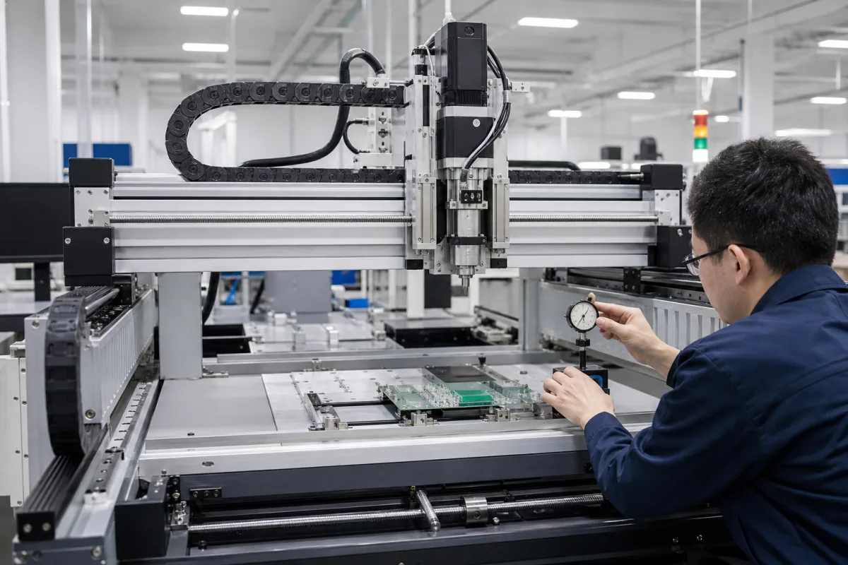
XY gantry system: ball-screw and belt Cartesian positioning module
Cartesian XY gantries · Ball-screw lead accuracy grades, belt versus screw drive, backlash, stroke, speed and payload
An XY gantry system is a pair of linear axes, each a carriage on guides driven by a ball screw or toothed belt and a servo or stepper motor, arranged at right angles so a tool or part can be placed anywhere in a rectangle. Ask three things first: which ball-screw accuracy grade or belt drive each axis uses and what travel error that allows over your stroke, whether backlash matters because the axes reverse, and what speed and payload the gantry holds at full stroke.
Two-axis XY Cartesian gantries and robots built from ball-screw or belt-driven linear modules, sold for dispensing, inspection, marking, assembly and similar positioning duties, including their drives, guides and motors. Complete surface-mount placement machines, with feeders, heads and vision, are covered on the SMT pick-and-place machine page. Gantry cranes, gantry machining centres and linear-motor stages are outside this page.
CNFX editorial research · Sources checked October 12, 2026 · 3 sources
Choose the ball-screw accuracy grade for the stroke
THK states that ball-screw lead accuracy is controlled under JIS B 1192 (ISO 3408): grades C0 to C5 are defined by representative travel distance error and fluctuation over the thread length, and C7 to C10 by travel distance error relative to 300 mm. Its rolled ball-screw allowances are ±50 µm/300 mm for C7, ±100 µm/300 mm for C8 and ±210 µm/300 mm for C10; THK lists grades 0, 1, 3 and 5 for positioning screws and 0, 1, 3, 5, 7 and 10 for transport screws. [1]
MISUMI's selection notes give the same C5 values (25 µm mean travel error, 20 µm variation for 315–400 mm), variation per 300 mm of 8 µm for C3 and 18 µm for C5, and 52 µm and 210 µm per 300 mm for its Ct7 and Ct10 transport screws. It says the grade is chosen by checking whether the screw's mean travel error is within the allowable positioning error. [2]
Editorial calculation: if a C7 rolled screw's ±50 µm allowance applied to each successive 300 mm, a 600 mm stroke could carry up to ±100 µm and a 1,200 mm stroke up to ±200 µm of lead error; a C10 screw over 1,200 mm could reach ±840 µm. Linear accumulation is a worst-case assumption; ask for a measured lead-error chart. [1]
Give the supplier the X and Y strokes, payload and its centre of gravity, required positioning accuracy and repeatability at the tool point, maximum speed and acceleration, cycle pattern (one-direction or reversing), mounting orientation, cantilever length of the tool, and the controller or signals you will use.
02
Decide between belt and ball-screw drive, and handle backlash
NUODUN's XY Cartesian robot page lists X/Y travel strokes of 600–1,250 mm depending on load, repeatability of ±0.01 to ±0.05 mm depending on drive type, speed up to 1,000 mm/s and payload up to 65 kg, and recommends that cantilever extension not exceed 400 mm. It describes belt drives as faster and lower cost for light tasks, and ball screws as giving higher precision and load capacity. [3]
MISUMI notes that axial clearance in the screw does not affect positioning accuracy if feed is in one direction, but produces backlash and degrades positioning accuracy when the direction or the axial load reverses, so clearance must be chosen against the accuracy requirement. Its procedure also asks buyers to check axial load, allowable rotational speed and life, then shaft rigidity and temperature effects when higher accuracy or response is needed. [2]
Editorial calculation: at 1,000 mm/s a ball screw with a 20 mm lead turns at 1,000 ÷ 20 × 60 = 3,000 rpm, and with a 10 mm lead at 6,000 rpm; check either against the screw's allowable rotational speed at the full stroke length before accepting a quoted top speed. Leads are assumed examples. [3][2]
03
Two-axis robots built from enclosed ball-screw or belt-driven actuators
The listing reviewed offers two-axis robots built from enclosed or semi-enclosed ball-screw actuators and belt-driven actuators, with stroke, speed and payload set per configuration.
04
Ball screw and nut, timing belt, linear guides, servo motors, beam and cable carriers
Part
Role
Fix in the order
Ball screw and nut
Converts motor rotation to travel; grade sets lead error. [1]
Stroke, cantilever, speed, payload and screw grade for an XY Cartesian module
Positioning accuracy is bounded by the screw grade: a rolled C7 screw allows ±50 µm per 300 mm of travel, so state the accuracy you need over the full stroke. [1]
Paste it into your enquiry below or into an email to a maker, then replace every bracket.
Strokes: [X; Y; Z if any]
Load: [payload; centre of gravity; cantilever]
Motion: [speed; acceleration; reversing or one-way]
Accuracy: [positioning; repeatability; measured where]
Drive: [belt or screw per axis; motor type; controller]
Site: [orientation; environment; supply]
1 company lists this product among what they make. Company figures are quoted from each
company's own website; every card states where the relationship came from.
NUODUN Linear
Manufacturing site to be confirmed for the order
Lists two-axis XY Cartesian robots with belt or ball-screw actuators, with stroke, speed and payload ranges.
Explore company information and manufacturing capabilities, then discuss the scope of your project with a relevant supplier.
Share this page
Compiled and source-reviewed by the CNFX editorial team.
Each manufacturer above links to the page on that company's own website where the product is listed, with the date we checked it. How we source and review
· Page last updated 13 October 2026
Buyer questions
What lead error does a C7 ball screw allow?
THK's table under JIS B 1192 (ISO 3408) allows ±50 µm per 300 mm for C7 rolled screws, ±100 µm for C8 and ±210 µm for C10. [1]
Belt or ball screw for an XY gantry?
NUODUN describes belt drives as faster and lower cost for light tasks and ball screws as giving higher precision and load capacity; it lists repeatability of ±0.01 to ±0.05 mm depending on drive type. [3]
Does screw clearance affect accuracy?
MISUMI says axial clearance does not affect one-direction feed but causes backlash when direction or load reverses. [2]
Sources and what still needs a direct check
Sources checked 2026-10-12. THK and MISUMI publish ball-screw selection data based on JIS B 1192 (ISO 3408). NUODUN is a linear-module maker describing its own gantries.