Editorial Technical Reference

Control Panel & PCB

This page explains how Control Panel & PCB is classified within Electrical Equipment Manufacturing. Technical values and manufacturer relationships are research references; confirm the current specification and supplier evidence for each order.

Technical Definition & Core Assembly

Integrated control interface and circuit board assembly for managing rectifier power supply operations
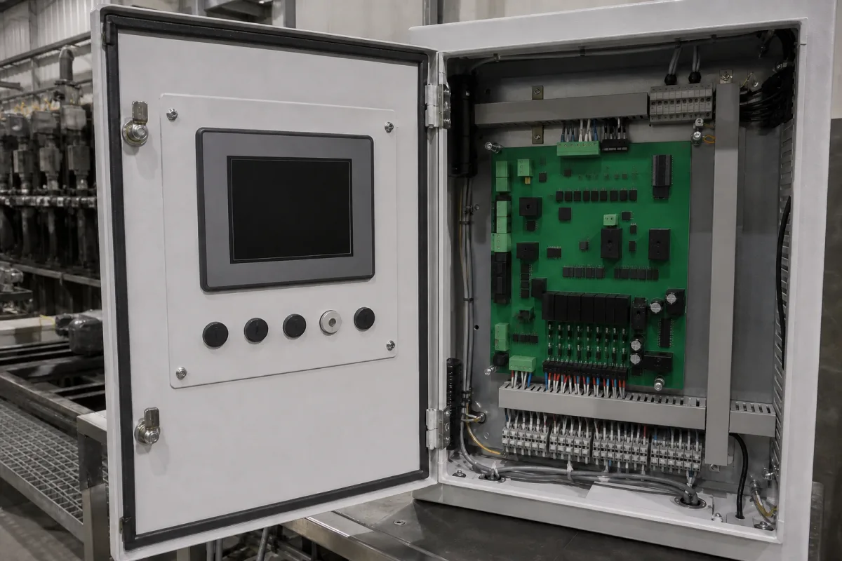
Representative product image. Confirm appearance and specifications with the manufacturer.

Product Specifications

Technical details and manufacturing context for Control Panel & PCB

Definition
The Control Panel & PCB is a combined assembly consisting of a control panel with user interface elements and a printed circuit board (PCB) that serves as the central control unit for a rectifier power supply system. This component manages power regulation, monitors operational parameters, provides user controls and displays, and coordinates the functions of other power supply components. The control panel typically includes buttons, switches, and displays for manual operation and monitoring, while the PCB contains electronic circuits that process control signals, implement logic functions, and interface with power components. Together, they receive input signals, process control algorithms, generate output signals to regulate rectifier operation, and provide feedback to operators. The assembly is designed for use in electrical equipment manufacturing, specifically for rectifier power supplies. Key specifications include an input voltage range of 85–264 V AC (per IEC 61000-4-5), adjustable output voltage up to 1000 V DC, output current up to 5000 A, and control accuracy of ±0.5%. Operating temperature ranges from -20 to 60°C (with derating above 50°C), storage temperature from -40 to 85°C, and humidity from 5 to 95% RH (non-condensing). The ingress protection rating is IP54–IP65, suitable for indoor/outdoor cabinets. The PCB is made of FR-4 glass epoxy with a thickness of 1.6 mm, copper thickness of 35–70 µm for high current traces, and board dimensions from 100×160 mm to 200×300 mm (per IEC 60297-3). The weight ranges from 0.5 to 2.5 kg depending on configuration. Materials include FR-4 substrate, copper traces, electronic components (ICs, resistors, capacitors), plastic/metal panel housing, and display elements (LEDs, LCD). These specifications are reference ranges and must be verified with the legal manufacturer for the specific model and application.
Working Principle
The control panel provides user interface elements such as buttons, switches, and displays for manual operation and monitoring. The PCB contains electronic circuits that process control signals, implement logic functions, and interface with power components. Together, they receive input signals, process control algorithms, generate output signals to regulate rectifier operation, and provide feedback to operators. The system manages power regulation, monitors operational parameters, and coordinates the functions of other power supply components.
Common Materials
FR-4 PCB substrate, Copper traces, Electronic components (ICs, resistors, capacitors), Plastic/metal panel housing, Display elements (LEDs, LCD)
Technical Parameters
ParameterTypical rangeNotes & selection driver
Input Voltage85–264 V ACWide range for global compatibilityIEC 61000-4-5
Output Voltage0–1000 V DCAdjustable for rectifier control
Output Current0–5000 AContinuous rating
Control Accuracy±0.5 %Voltage and current regulation
Operating Temperature-20–60 °CDerating above 50°CIEC 60068-2-1/2
Storage Temperature-40–85 °CNon-operationalIEC 60068-2-1/2
Humidity5–95 % RHNon-condensingIEC 60068-2-78
Ingress ProtectionIP54–IP65For indoor/outdoor cabinetsIEC 60529
PCB MaterialFR-4Glass epoxy, 1.6mm thicknessIPC-4101
Copper Thickness35–70 µmFor high current tracesIPC-6012
Board Dimensions100×160–200×300 mmCustom sizes availableIEC 60297-3
Weight0.5–2.5 kgDepending on configuration

Ranges are indicative industry figures for RFQ preparation, not a supplier commitment. Confirm every value and standard with the legal manufacturer before ordering.

Components / BOM
  • Microcontroller Unit
    Processes control algorithms and manages system operations
    Material: Semiconductor silicon
  • Power Regulation Circuit
    Converts and regulates power for control electronics
    Material: Electronic components on PCB
  • Interface Connectors Part
    Provides electrical connections to other power supply components
    Material: Copper alloy with plastic housing
  • Display Panel
    Shows operational parameters and system status
    Material: Glass/plastic with electronic display elements
  • Buttons and Switches
    The manual inputs the operator actually presses.

Applied To / Applications

This component is essential for the following industrial systems and equipment:

Industrial Ecosystem & Supply Chain Structure

Complementary Systems
Downstream Applications
Specialized Tooling

Application Fit & Sizing Matrix

Operational Limits
pressure: Atmospheric only (non-pressurized enclosure)
other spec: IP54 ingress protection, 85% RH max humidity, 5-95% non-condensing
temperature: -20°C to +60°C (operating), -40°C to +85°C (storage)
Media Compatibility
✓ Clean industrial air environments ✓ Dry control rooms ✓ Enclosed electrical cabinets with filtered ventilation
Unsuitable: Wet/high humidity areas, corrosive chemical atmospheres, or locations with conductive dust/particulates
Sizing Data Required
  • Rectifier output power rating (kW/kVA)
  • Control interface requirements (I/O count, communication protocols)
  • Enclosure dimensions and panel cutout specifications

Reliability & Engineering Risk Analysis

Failure Mode & Root Cause
Overheating
Cause: Inadequate ventilation, dust accumulation, or excessive current draw leading to thermal stress on components.
Corrosion
Cause: Exposure to moisture, humidity, or corrosive chemicals causing oxidation or short circuits on PCB traces and connectors.
Maintenance Indicators
  • Burning smell or visible smoke from the control panel
  • Intermittent operation or unexpected shutdowns of connected equipment
Engineering Tips
  • Implement regular cleaning schedules with compressed air to remove dust and ensure proper airflow around components.
  • Apply conformal coating to PCBs and use sealed enclosures in environments with high humidity or chemical exposure.

Indicative industry ranges for design and RFQ preparation. Confirm the exact figures and applicable standard with the manufacturer before specifying.

Compliance & Manufacturing Standards

Applicable Standards
IEC 61439-1: Low-voltage switchgear and controlgear assemblies IPC-A-610: Acceptability of Electronic Assemblies EN 60204-1: Safety of machinery - Electrical equipment of machines

Quoted from the published standard.

Manufacturing Precision
  • PCB trace width tolerance: +/-10%
  • Control panel mounting hole position tolerance: +/-0.5mm
Quality Inspection
  • In-Circuit Test (ICT) for PCB electrical continuity
  • Dielectric withstand test (hipot test) for control panel insulation

Manufacturers of Control Panel & PCB

Manufacturer profiles associated with Control Panel & PCB.

Sourcing Control Panel & PCB from China?
Tell us your specification and target quantity — we will match it against manufacturer records and come back with the factories that fit.
Request manufacturers We manufacture this

Manufacturer listings support early research and capability understanding. They are not certification, ranking, or transaction guarantees.

Technical documentation
Request current drawings, revision history, and a signed specification sheet.
Manufacturing capability
Verify equipment lists, process limits, capacity, and representative production evidence.
Inspection readiness
Confirm test methods, calibrated equipment, sampling plans, and traceable reports.
Supplier transparency
Check the legal entity, factory address, ownership, certifications, and direct contacts.

CNFX does not score or rank suppliers. Buyers must verify all claims and documents with the legal manufacturer before ordering.

Supply Chain Compatible Machinery & Devices

Circuit Breaker Arc Chute

The Circuit Breaker Arc Chute is a critical safety component in electrical circuit breakers, designed to rapidly extinguish electric arcs that form during circuit interruption.

Explore Specs →
Medium Voltage Switchgear Assembly Line

Automated production system for assembling medium voltage electrical switchgear.

Explore Specs →
Motor Terminal Block

A motor terminal block is a standardized electrical component that provides secure, insulated connection points for motor winding leads.

Explore Specs →
PLC Control System

A digital industrial computer control system that monitors inputs, makes decisions based on a custom program, and controls outputs to automate industrial processes.

Explore Specs →

Frequently Asked Questions

What is the function of the Control Panel & PCB in a rectifier power supply?

The Control Panel & PCB serves as the central control unit. It manages power regulation, monitors operational parameters, provides user controls and displays, and coordinates the functions of other power supply components. The control panel allows manual operation and monitoring, while the PCB processes control signals and implements logic functions.

What are the key electrical specifications for this component?

The input voltage range is 85–264 V AC (per IEC 61000-4-5). The output voltage is adjustable from 0 to 1000 V DC, and the output current is rated from 0 to 5000 A. Control accuracy is ±0.5%. These are reference ranges; verify with the manufacturer for the specific model.

What environmental conditions can this component withstand?

Operating temperature is -20 to 60°C with derating above 50°C. Storage temperature is -40 to 85°C. Humidity range is 5 to 95% RH non-condensing. Ingress protection is IP54–IP65, suitable for indoor/outdoor cabinets. Standards referenced include IEC 60068-2-1/2 and IEC 60068-2-78.

What materials and construction are used for the PCB?

The PCB substrate is FR-4 glass epoxy with a thickness of 1.6 mm. Copper thickness is 35–70 µm for high current traces. Board dimensions range from 100×160 mm to 200×300 mm (per IEC 60297-3). Materials include copper traces, electronic components (ICs, resistors, capacitors), plastic/metal panel housing, and display elements (LEDs, LCD).

Data Basis

Editorial classification, named public sources where available, and source-reviewed manufacturer records.

Preliminary Technical Classification
This page supports structured research, RFQ preparation, and supplier evaluation. It does not replace buyer-led supplier qualification, standards review, or technical approval.
Buyer enquiry

Request manufacturing insight for Control Panel & PCB

Ask for use case, specification boundaries, supplier type, and RFQ preparation information for this product.

Where it goes
Straight to the CNFX editorial desk, and to the manufacturer if this product is linked to a claimed profile. Nothing is broadcast to a supplier list.
Your details stay here
We do not sell or rent enquiry data, and we do not add you to a mailing list. Used only to answer this request.
No commission, no middleman
CNFX is a directory. We take no cut of any order and never negotiate on a supplier's behalf.
What we don't claim
A listing is not an endorsement. Qualify every supplier and verify every figure yourself before ordering.

Your business information is used only to process this request.

Thank you! Your message has been sent. We'll respond within 1–3 business days.
Sorry, we couldn't send your message. Please try again, or email us at contact@cnfx.com.

Need to Manufacture Control Panel & PCB?

Compare manufacturer profiles with relevant product and process capability.

Previous Product
Wire Tensioning System
Last Product
Get QuotesChat