Editorial Technical Reference

Final Test Chamber

This page explains how Final Test Chamber is classified within Electrical Equipment Manufacturing. Technical values and manufacturer relationships are research references; confirm the current specification and supplier evidence for each order.

Technical Definition & Core Assembly

A controlled enclosure for final performance verification of medium voltage switchgear before shipment.
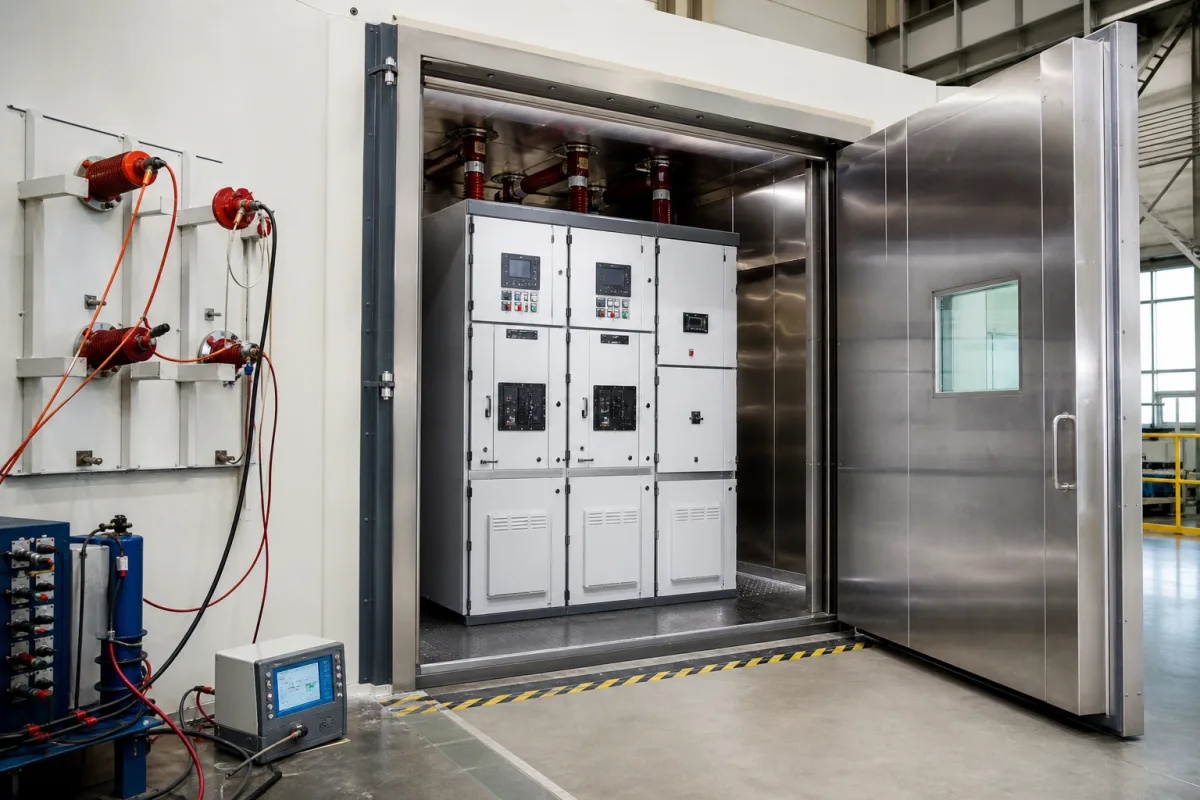
Final Test Chamber in a manufacturing environment
Representative product image. Confirm appearance and specifications with the manufacturer.

Product Specifications

Technical details and manufacturing context for Final Test Chamber

Definition
The Final Test Chamber is a component of the Medium Voltage Switchgear Assembly Line, providing a controlled environment where fully assembled switchgear units undergo comprehensive electrical, mechanical, and safety testing. This chamber ensures that each unit meets specified performance standards, regulatory requirements, and quality benchmarks before customer delivery. It is designed to accommodate medium voltage switchgear up to 12 kV, with internal dimensions of 3000×3000×2500 mm (W×D×H). The chamber supports a maximum test voltage of 42 kV at power frequency, per IEC 62271-1, and operates at test frequencies of 50–60 Hz, per IEC 60060-1. It maintains an ambient temperature range of -5 to 55 °C and relative humidity of 20–80% RH (non-condensing). The enclosure has an IP54 rating per IEC 60529, providing dust and splash protection. Power supply is three-phase, 380 V AC ±10%, 50/60 Hz, per IEC 60038. For primary injection testing, it supports a maximum current capacity of 6300 A per IEC 62271-1. Measurement accuracy is ±0.5% per IEC 60051 for voltage, current, and resistance measurements. Leakage current is limited to ≤10 mA at rated voltage per IEC 62271-1. The chamber is constructed with galvanized steel, insulated panels, and safety glass viewports; interior panels are made of corrosion-resistant 304 stainless steel per ASTM A240. The footprint, including access and ventilation clearances, is 3500×3500 mm. The working principle involves a secure, isolated space with integrated high-voltage test equipment, measurement instruments, and safety systems. Technicians connect the assembled switchgear to test sources within the chamber to simulate operational conditions, verifying parameters such as insulation resistance, dielectric strength, circuit breaker timing, protective relay functionality, and overall system integrity under controlled and safe conditions. This chamber is essential for quality assurance in electrical equipment manufacturing. Always verify model-specific values and standards with the legal manufacturer or supplier.
Working Principle
The chamber provides a secure, isolated space equipped with integrated high-voltage test equipment, measurement instruments, and safety systems. Technicians connect the assembled switchgear to test sources within the chamber to simulate operational conditions. This allows verification of insulation resistance, dielectric strength, circuit breaker timing, protective relay functionality, and overall system integrity under controlled and safe conditions. The chamber's design ensures that tests are performed within specified environmental parameters, such as temperature and humidity, to maintain accuracy and safety.
Common Materials
Galvanized steel, Insulated panels, Safety glass viewports
Technical Parameters
ParameterTypical rangeNotes & selection driver
Internal Dimensions (W×D×H)3000×3000×2500 mmAccommodates medium voltage switchgear up to 12 kV
Maximum Test Voltage42 kVPower frequency withstand voltage for 12 kV equipmentIEC 62271-1
Test Frequency50–60 HzMains frequency for dielectric testsIEC 60060-1
Temperature Range-5–55 °COperating ambient for test chamber
Relative Humidity20–80 % RHNon-condensing; affects insulation performance
IP RatingIP54Dust and splash protection for internal equipmentIEC 60529
Power Supply380±10% V ACThree-phase, 50/60 HzIEC 60038
Maximum Current Capacity6300 AFor primary injection testingIEC 62271-1
Measurement Accuracy±0.5 %For voltage, current, and resistance measurementsIEC 60051
Leakage Current Limit≤10 mAAt rated voltage; ensures safetyIEC 62271-1
Chamber Material304 SSCorrosion-resistant steel for interior panelsASTM A240
Footprint (L×W)3500×3500 mmIncludes access and ventilation clearances

Ranges are indicative industry figures for RFQ preparation, not a supplier commitment. Confirm every value and standard with the legal manufacturer before ordering.

Components / BOM
  • Chamber Body
    The chamber shell itself: encloses the process volume and carries the operating pressure and temperature.
  • High-Voltage Test Transformer
    Generates the required AC/DC high voltage for dielectric withstand and insulation tests.
  • Measurement and Control Panel
    Houses instruments (voltmeters, ammeters, timers) and controls for test sequencing and data logging.
  • Safety Barrier and Door Interlock
    Physical barrier and electrical interlock to prevent access during live testing, ensuring operator safety.

Applied To / Applications

This component is essential for the following industrial systems and equipment:

Industrial Ecosystem & Supply Chain Structure

Complementary Systems
Downstream Applications
Specialized Tooling

Application Fit & Sizing Matrix

Operational Limits
pressure: Atmospheric to 1.2 bar absolute (sealed chamber)
flow rate: N/A (static test environment)
temperature: -20°C to +50°C (operating), -40°C to +70°C (storage)
humidity range: 10% to 95% RH (non-condensing)
electrical clearance: Per IEEE C37.20.2 for medium voltage
slurry concentration: N/A (dry testing only)
Media Compatibility
✓ SF6 gas insulation testing ✓ Dry compressed air systems ✓ Nitrogen purge environments
Unsuitable: Corrosive salt fog or acidic atmospheres (accelerated corrosion testing)
Sizing Data Required
  • Maximum switchgear dimensions (LxWxH)
  • Rated voltage and BIL requirements
  • Required test sequence duration and cycle count

Reliability & Engineering Risk Analysis

Failure Mode & Root Cause
Temperature sensor drift
Cause: Prolonged exposure to extreme thermal cycling causing calibration degradation or sensor element fatigue
Humidity control system failure
Cause: Corrosion of humidifier/dehumidifier components due to mineral buildup from water quality issues or condensation management problems
Maintenance Indicators
  • Inconsistent temperature readings between multiple sensors (≥2°C deviation)
  • Audible compressor strain or frequent cycling with inadequate temperature/humidity recovery
Engineering Tips
  • Implement quarterly calibration verification using NIST-traceable references and maintain detailed drift trend analysis
  • Install dual-stage water filtration (5μm sediment + deionization) and establish preventive maintenance for condensation drainage systems

Indicative industry ranges for design and RFQ preparation. Confirm the exact figures and applicable standard with the manufacturer before specifying.

Compliance & Manufacturing Standards

Applicable Standards
ISO 17025:2017 - General requirements for the competence of testing and calibration laboratories IEC 60068-2-1:2007 - Environmental testing - Part 2-1: Tests - Test A: Cold

Quoted from the published standard.

Manufacturing Precision
  • Temperature Uniformity: +/-0.5°C across chamber volume
  • Pressure Leak Rate: <0.1 mbar/min at maximum operating pressure
Quality Inspection
  • Temperature Mapping and Calibration Verification
  • Electrical Safety and Grounding Continuity Test

Manufacturers of Final Test Chamber

Manufacturer profiles associated with Final Test Chamber.

Sourcing Final Test Chamber from China?
Tell us your specification and target quantity — we will match it against manufacturer records and come back with the factories that fit.
Request manufacturers We manufacture this

Manufacturer listings support early research and capability understanding. They are not certification, ranking, or transaction guarantees.

Share this page
Technical documentation
Request current drawings, revision history, and a signed specification sheet.
Manufacturing capability
Verify equipment lists, process limits, capacity, and representative production evidence.
Inspection readiness
Confirm test methods, calibrated equipment, sampling plans, and traceable reports.
Supplier transparency
Check the legal entity, factory address, ownership, certifications, and direct contacts.

CNFX does not score or rank suppliers. Buyers must verify all claims and documents with the legal manufacturer before ordering.

Supply Chain Compatible Machinery & Devices

Circuit Breaker Arc Chute

The Circuit Breaker Arc Chute is a critical safety component in electrical circuit breakers, designed to rapidly extinguish electric arcs that form during circuit interruption.

Explore Specs →
Medium Voltage Switchgear Assembly Line

Automated production system for assembling medium voltage electrical switchgear.

Explore Specs →
Motor Terminal Block

A motor terminal block is a standardized electrical component that provides secure, insulated connection points for motor winding leads.

Explore Specs →
PLC Control System

A digital industrial computer control system that monitors inputs, makes decisions based on a custom program, and controls outputs to automate industrial processes.

Explore Specs →

Frequently Asked Questions

What is the maximum voltage rating for switchgear tested in this chamber?

The chamber accommodates medium voltage switchgear up to 12 kV, with a maximum test voltage of 42 kV at power frequency per IEC 62271-1.

What environmental conditions does the chamber maintain?

The chamber operates within a temperature range of -5 to 55 °C and relative humidity of 20–80% RH (non-condensing). These conditions are maintained to ensure accurate testing.

What safety features are included?

The chamber has an IP54 rating for dust and splash protection, safety glass viewports, and a leakage current limit of ≤10 mA at rated voltage per IEC 62271-1.

What standards are referenced for testing?

Key standards include IEC 62271-1 for switchgear testing, IEC 60060-1 for high-voltage test techniques, IEC 60529 for enclosure protection, IEC 60038 for voltage ratings, IEC 60051 for measurement instruments, and ASTM A240 for stainless steel material.

Data Basis

Editorial classification, named public sources where available, and source-reviewed manufacturer records.

Preliminary Technical Classification
This page supports structured research, RFQ preparation, and supplier evaluation. It does not replace buyer-led supplier qualification, standards review, or technical approval.
Buyer enquiry

Request manufacturing insight for Final Test Chamber

Ask for use case, specification boundaries, supplier type, and RFQ preparation information for this product.

Where it goes
Straight to the CNFX editorial desk, and to the manufacturer if this product is linked to a claimed profile. Nothing is broadcast to a supplier list.
Your details stay here
We do not sell or rent enquiry data, and we do not add you to a mailing list. Used only to answer this request.
No commission, no middleman
CNFX is a directory. We take no cut of any order and never negotiate on a supplier's behalf.
What we don't claim
A listing is not an endorsement. Qualify every supplier and verify every figure yourself before ordering.

Your business information is used only to process this request.

Thank you! Your message has been sent. We'll respond within 1–3 business days.
Sorry, we couldn't send your message. Please try again, or email us at [email protected].

Need to Manufacture Final Test Chamber?

Compare manufacturer profiles with relevant product and process capability.

Previous Product
Wire Tensioning System
Last Product
Get QuotesChat