Editorial Technical Reference

Grounding Verification Sensor

This page explains how Grounding Verification Sensor is classified within Electrical Equipment Manufacturing. Technical values and manufacturer relationships are research references; confirm the current specification and supplier evidence for each order.

Technical Definition & Core Assembly

A safety device that detects and verifies proper electrical grounding in industrial equipment.
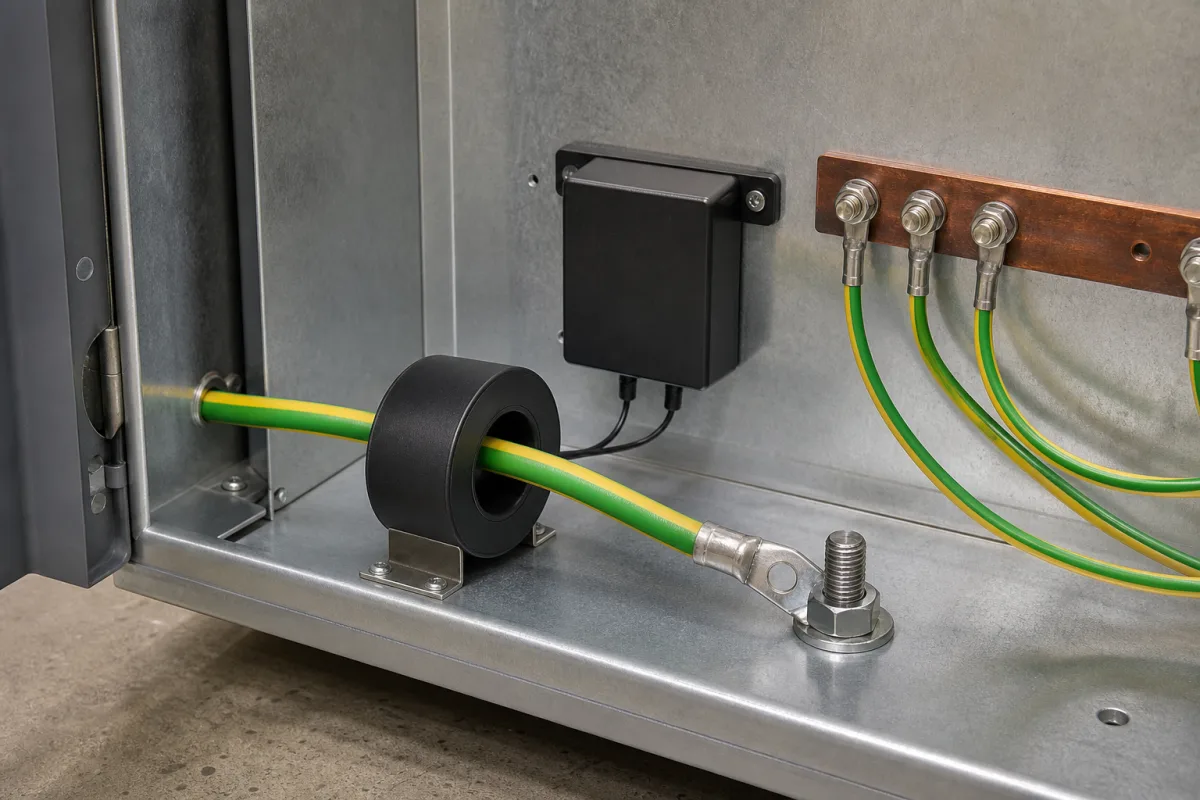
Representative product image. Confirm appearance and specifications with the manufacturer.

Product Specifications

Technical details and manufacturing context for Grounding Verification Sensor

Definition
The Grounding Verification Sensor is a component used in electrical equipment manufacturing, specifically within safety interlock systems. Its primary function is to continuously monitor and confirm the integrity of electrical grounding connections on industrial machinery. By measuring the electrical resistance between the equipment chassis and earth ground, the sensor ensures that grounding is sufficient and uncompromised. If the resistance exceeds a preset safety threshold, indicating poor grounding, the sensor sends a signal to the interlock system to prevent equipment activation or trigger a shutdown, thereby protecting personnel from electrical shock hazards and supporting compliance with safety standards such as IEC 60364-6. The sensor is housed in a corrosion-resistant stainless steel (316L) enclosure with copper alloy contacts and epoxy encapsulation, ensuring durability in industrial environments. It operates on a 24 V DC supply (with ±10% tolerance) and consumes no more than 2 W. The device features a response time of ≤0.1 seconds to alarm after a ground fault, and its detection resistance threshold is set at ≤10 Ω. It provides a 4–20 mA analog current loop output, conforming to IEC 60381-1, and connects via a 4-pin M12 connector per IEC 61076-2-101. The sensor is designed for a wide operating temperature range of -40 to 85 °C and can be stored at -40 to 105 °C, meeting IEC 60068-2-1/2. With an ingress protection rating of IP67 (IEC 60529), it is dust-tight and protected against immersion. Cable lengths from 2 to 10 meters are available, with weight ranging from 0.5 to 1.2 kg depending on cable length. All specifications are reference values; users must verify model-specific parameters and standards with the legal manufacturer or supplier.
Working Principle
The sensor measures the electrical resistance between the equipment chassis and earth ground using its copper alloy contacts. It compares this resistance against a preset threshold (≤10 Ω). If the resistance exceeds this limit, indicating inadequate grounding, the sensor triggers an alarm within 0.1 seconds. This signal is sent to the interlock system, which then prevents equipment activation or initiates a shutdown procedure. The sensor operates on a 24 V DC supply and outputs a 4–20 mA analog signal proportional to the grounding status. Its stainless steel housing and epoxy encapsulation protect internal components from environmental factors, ensuring reliable operation across the specified temperature range.
Common Materials
Stainless Steel Housing, Copper Alloy Contacts, Epoxy Encapsulation
Technical Parameters
ParameterTypical rangeNotes & selection driver
Detection Resistance Threshold≤10 ΩGround resistance above threshold triggers alarmIEC 60364-6
Response Time≤0.1 sTime to alarm after ground fault
Supply Voltage24 ±10% V DCReverse polarity protected
Power Consumption≤2 WAt nominal voltage
Operating Temperature-40–85 °CExtended range for industrial useIEC 60068-2-1/2
Storage Temperature-40–105 °CNon-operatingIEC 60068-2-1/2
Ingress ProtectionIP67Dust-tight and protected against immersionIEC 60529
Housing Material316LCorrosion-resistant stainless steelASTM A240
Cable Length2–10 mCustom lengths available
Weight0.5–1.2 kgDepending on cable length
Output Signal4–20 mAAnalog current loopIEC 60381-1
Electrical ConnectionM124-pin connectorIEC 61076-2-101

Ranges are indicative industry figures for RFQ preparation, not a supplier commitment. Confirm every value and standard with the legal manufacturer before ordering.

Components / BOM
  • Resistance Measurement Circuit
    Measures electrical resistance between equipment and ground
    Material: Printed Circuit Board with precision resistors
  • Signal Conditioning Module
    Processes raw measurements and compares to thresholds
    Material: Integrated Circuit with analog/digital converters
  • Output Relay
    Provides contact closure signal to interlock system
    Material: Electromechanical relay with silver contacts
  • Test Button Part
    Allows manual verification of sensor functionality
    Material: Polycarbonate button with stainless steel spring
  • Measurement Contacts
    The probes that actually touch the chassis and earth; the resistance is measured across them.
    Material: Copper alloy
  • Stainless Steel Housing
    Encloses and encapsulates the electronics against the plant environment.
    Material: Stainless steel

Applied To / Applications

This component is essential for the following industrial systems and equipment:

Industrial Ecosystem & Supply Chain Structure

Complementary Systems
Downstream Applications
Specialized Tooling

Application Fit & Sizing Matrix

Operational Limits
pressure: 0 to 10 bar
other spec: IP67 rating, 24V DC power supply, 4-20mA output signal
temperature: -40°C to +85°C
Media Compatibility
✓ Industrial machinery frames ✓ Electrical enclosures ✓ Conductive metal structures
Unsuitable: High-voltage direct contact environments (>1000V)
Sizing Data Required
  • Grounding conductor size (AWG/mm²)
  • Required verification response time (ms)
  • Installation environment classification (e.g., Zone 0/1/2 for hazardous areas)

Reliability & Engineering Risk Analysis

Failure Mode & Root Cause
Sensor Drift/Calibration Loss
Cause: Environmental factors (temperature fluctuations, humidity), component aging, or electrical interference affecting measurement accuracy over time.
Physical Damage/Connection Failure
Cause: Mechanical stress from vibration, improper installation, corrosion at contact points, or cable wear compromising signal integrity.
Maintenance Indicators
  • Inconsistent or erratic grounding resistance readings during routine checks
  • Visible corrosion, loose connections, or physical damage to sensor housing or wiring
Engineering Tips
  • Implement regular calibration schedules using certified test equipment and maintain environmental controls to minimize drift
  • Use vibration-dampening mounts, corrosion-resistant materials, and strain relief on cables during installation

Indicative industry ranges for design and RFQ preparation. Confirm the exact figures and applicable standard with the manufacturer before specifying.

Compliance & Manufacturing Standards

Applicable Standards
IEC 61010-1 Safety requirements for electrical equipment ANSI/ISA-12.12.01 Electrical Equipment for Hazardous Locations

Quoted from the published standard.

Manufacturing Precision
  • Measurement accuracy: +/-0.5% of full scale
  • Response time: +/-10 milliseconds
Quality Inspection
  • Environmental sealing test (IP67/IP68)
  • Calibration verification against NIST-traceable standards

Manufacturers of Grounding Verification Sensor

Manufacturer profiles associated with Grounding Verification Sensor.

Sourcing Grounding Verification Sensor from China?
Tell us your specification and target quantity — we will match it against manufacturer records and come back with the factories that fit.
Request manufacturers We manufacture this

Manufacturer listings support early research and capability understanding. They are not certification, ranking, or transaction guarantees.

Technical documentation
Request current drawings, revision history, and a signed specification sheet.
Manufacturing capability
Verify equipment lists, process limits, capacity, and representative production evidence.
Inspection readiness
Confirm test methods, calibrated equipment, sampling plans, and traceable reports.
Supplier transparency
Check the legal entity, factory address, ownership, certifications, and direct contacts.

CNFX does not score or rank suppliers. Buyers must verify all claims and documents with the legal manufacturer before ordering.

Supply Chain Compatible Machinery & Devices

Circuit Breaker Arc Chute

The Circuit Breaker Arc Chute is a critical safety component in electrical circuit breakers, designed to rapidly extinguish electric arcs that form during circuit interruption.

Explore Specs →
Medium Voltage Switchgear Assembly Line

Automated production system for assembling medium voltage electrical switchgear.

Explore Specs →
Motor Terminal Block

A motor terminal block is a standardized electrical component that provides secure, insulated connection points for motor winding leads.

Explore Specs →
PLC Control System

A digital industrial computer control system that monitors inputs, makes decisions based on a custom program, and controls outputs to automate industrial processes.

Explore Specs →

Frequently Asked Questions

What is the detection resistance threshold of the Grounding Verification Sensor?

The detection resistance threshold is ≤10 Ω, as per IEC 60364-6. If the measured ground resistance exceeds this value, the sensor triggers an alarm to indicate poor grounding.

What is the response time of the sensor after a ground fault?

The response time is ≤0.1 seconds. This ensures rapid detection and alarm to allow the interlock system to act quickly in preventing equipment operation.

What are the environmental ratings for this sensor?

The sensor has an operating temperature range of -40 to 85 °C and a storage range of -40 to 105 °C, per IEC 60068-2-1/2. It also has an IP67 ingress protection rating (IEC 60529), making it dust-tight and protected against immersion.

What output signal does the sensor provide?

The sensor provides a 4–20 mA analog current loop output, conforming to IEC 60381-1. This signal can be used for monitoring or integration with control systems.

Data Basis

Editorial classification, named public sources where available, and source-reviewed manufacturer records.

Preliminary Technical Classification
This page supports structured research, RFQ preparation, and supplier evaluation. It does not replace buyer-led supplier qualification, standards review, or technical approval.
Buyer enquiry

Request manufacturing insight for Grounding Verification Sensor

Ask for use case, specification boundaries, supplier type, and RFQ preparation information for this product.

Where it goes
Straight to the CNFX editorial desk, and to the manufacturer if this product is linked to a claimed profile. Nothing is broadcast to a supplier list.
Your details stay here
We do not sell or rent enquiry data, and we do not add you to a mailing list. Used only to answer this request.
No commission, no middleman
CNFX is a directory. We take no cut of any order and never negotiate on a supplier's behalf.
What we don't claim
A listing is not an endorsement. Qualify every supplier and verify every figure yourself before ordering.

Your business information is used only to process this request.

Thank you! Your message has been sent. We'll respond within 1–3 business days.
Sorry, we couldn't send your message. Please try again, or email us at contact@cnfx.com.

Need to Manufacture Grounding Verification Sensor?

Compare manufacturer profiles with relevant product and process capability.

Previous Product
Wire Tensioning System
Last Product
Get QuotesChat