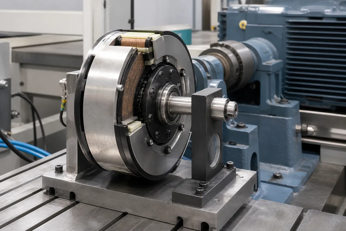
Electromagnetic clutches and brakes · Torque with safety factor, stopping time and inertia, heat per cycle, run-in, DC switching
An industrial electromagnetic clutch-brake unit uses DC coils to pull a steel armature against a friction face, either to couple a driven shaft to a running motor (clutch) or to stop and hold it (brake), and the two can be combined in one housing for start-stop and indexing drives. Ask three things first: what torque the unit must transmit including load friction and inertia, how much heat each start or stop generates at your cycle rate, and how it is switched and run in to reach rated torque and response.
Electromagnetically actuated single-disc, multi-disc and tooth clutches and brakes, power-on and spring-applied (electrically released), and clutch-brake combinations for industrial drives. Pneumatic, hydraulic and mechanical clutches, motor brakes sold only as motor options, and vehicle clutches are outside this page.
CNFX editorial research · Sources checked October 18, 2026 · 5 sources
Warner Electric's sizing guide lists, in order, transmissible torque, energy source, actuation mode, operating environment, heat dissipation and mounting orientation. It distinguishes static torque (at zero relative speed), dynamic torque during acceleration or deceleration, and residual torque in non-energised multi-disc units. Nominal torque is Mn = 9550 · P / n (Nm, kW, min⁻¹); where the real torque is unknown it multiplies this by a safety factor K of 2.5–3 for electric motors, 4–5 for diesel engines and 5–6 for compressors. [1]
For an accurate selection it adds the load torque Ml to the acceleration or deceleration torque Md = J · n / (9.55 · t), where J is the total inertia in kg·m² including reflected inertias and the unit's own parts; the unit's nominal torque must exceed the total. The real time is t = J · n / (9.55 · (Mn ± Ml)), with minus for a clutch and plus for a brake. It permits tooth clutches only for engagement at zero speed difference, applies K = 3 to power-on tooth devices, and forbids them for lifting. [1]
Editorial calculation: assume 2.2 kW is the mechanical shaft power at 1,450 min⁻¹ and apply only Warner’s quick-selection factor for an electric-motor drive. Then 9550 × 2.2/1450 ≈ 14.5 Nm; multiplying by the stated 2.5–3 gives approximately 36–43 Nm. In a separate hypothetical stop, assume constant 40 Nm dynamic brake torque, total reflected inertia 0.05 kg·m² at that shaft, initial speed 1,450 min⁻¹ and constant 2 Nm friction assisting the stop. The catalogue model gives 0.05 × 1450/(9.55 × 42) ≈ 0.18 s. This excludes coil/control delay, torque build-up, speed-dependent friction and elastic motion; it is not a measured machine stopping time or a selected brake rating. [1]
Give the supplier the drive power and speed, load torque, total inertia at the unit's shaft, required start and stop times, cycles per minute, mounting (shaft, flange, motor C-face) and orientation, environment (dry, oil, dust), supply voltage and switching, and whether the brake must hold on power loss.
02
Check heat per cycle, run-in and switching
Warner Electric states that friction turns mechanical energy into heat that the unit must absorb without damage, and gives the energy per engagement as W = (J · n² / 182.5) · (Mn / (Mn ± Ml)) joules, to be checked against each product's heat dissipation diagram; if size by heat differs from size by torque, it advises the larger. Dry units are recommended for −25 to +40 °C; lubricated multi-disc units suit high energy per cycle, with oil below 40 cSt at 50 °C. [1]
It notes that friction torque ratings assume 'run in' conditions: new units may transmit below 50% of nominal torque, reached after a run-in of repeated operations with a differential speed above 1 m/s, so a run-in is recommended for positioning precision and rapid acceleration. Its electric units run on DC or rectified AC at standard 24, 103.5 and 207 V; switching on the AC side is 5 to 6 times slower than on the DC side, some electrically released devices use a bi-voltage supply, such as 103.5/48 or 207/103.5 V DC, with the higher voltage for the initial armature actuation and the lower to retain that armature position; for an electrically released brake, energisation releases the brake rather than applying braking torque, and the back EMF at switch-off should be suppressed. [1]
Editorial heat arithmetic: under the same constant-torque stopping assumptions, with the 2 Nm load friction opposing rotation and assisting deceleration, Warner’s energy expression gives approximately 549 J per brake stop (about 550 J). Assume exactly 10 identical stops each minute, no other clutch/brake heating and stable repeated operation: average brake dissipation is approximately 5.49 kJ/min, or 91 W (about 90 W). Average power alone does not establish the permissible engagement energy, peak temperature or cooling interval; check both per-cycle and duty limits on the selected unit’s curves. The 0.18 s mechanical model is not a press safeguarding input. [1]
03
Compare combined clutch-brake units with spring-applied brakes
Kendrion's INTORQ 14.800 is a ready-to-install clutch-brake combination in a single housing for clocked drives at mains-synchronised motor speed: dry-running, backlash-free, engaged by applied DC voltage, in five sizes with rated torques from 7.5 to 120 Nm, insulation temperature class B (130 °C) and a patented wear-adjustment mechanism for resetting the air gap. [2]
Where the drive must hold or stop when power is lost, Kendrion's spring-applied (fail-safe) brakes cover torque from 0.22 Nm (Servo Line, for servo motors) through 1.5–600 Nm (BFK458, for IEC gear motors) and 4–125 Nm (BFK457, for industrial trucks and AGVs) to 100–2,400 Nm (BFK468, for hoists and demanding emergency stops). [3]
The series torque spans do not select a unit for the preceding drive example. Confirm power-loss action, dynamic versus holding duty, permissible energy, speed, mounting, wear condition and control supply for the specific size. A spring-applied operating principle alone does not establish the safety performance of the complete machine. [2][3]
04
Check stopping time where the unit drives a power press
For applicable US mechanical power presses, OSHA specifies brake capability and part-revolution clutch/control behaviour. This is a complete-machine requirement; a generic clutch-brake torque rating does not establish press compliance. [4][5]
OSHA distinguishes presence-sensing/two-hand-control provisions from PSDI operation. The PSDI distance rule includes sensor and intervening-control response, brake-monitor allowance and penetration depth, with specified stopping-time measurements. Do not use the simplified distance expression for a PSDI installation. [5]
Obtain the press integrator’s measured stop-time record, applicable safeguarding calculation and brake-monitor validation for the operating mode. The catalogue’s mechanical deceleration estimate excludes control and actuation delays. [5]
05
Sunrise’s electromagnetic clutch and brake assemblies
Sunrise lists FMP and FMT electromagnetic clutch-brake assemblies alongside separate clutches and brakes. Confirm the actual assembly’s power-on or spring-applied state, allowed duty and supplied controls; the Warner and Kendrion examples are not Sunrise ratings.
06
Field coil, armature, torque interface and control supply
Measured complete-press response and safeguarding depend on operating mode; do not substitute catalogue mechanical deceleration. [5]
Measured stop time at 90° and brake-monitor interface.
08
Send the drive, load and cycle data together
Paste it into your enquiry below or into an email to a maker, then replace every bracket.
Drive: [power; speed; motor or engine]
Load: [load torque; inertia at unit shaft]
Motion: [start and stop times; cycles per minute]
Unit: [clutch; brake; combination; power-on or spring-applied]
Mounting: [shaft; flange; orientation; environment]
Electrics: [supply; DC switching; overexcitation]
1 company lists this product among what they make. Company figures are quoted from each
company's own website; every card states where the relationship came from.
SUNRISE GROUP
TBC
Lists FMP and FMT electromagnetic clutch-brake assemblies, separately from pneumatic and powder clutch/brake ranges.
Explore company information and manufacturing capabilities, then discuss the scope of your project with a relevant supplier.
Share this page
Compiled and source-reviewed by the CNFX editorial team.
Each manufacturer above links to the page on that company's own website where the product is listed, with the date we checked it. How we source and review
· Page last updated 13 October 2026
Buyer questions
How much torque does a clutch for an electric motor need?
Warner Electric's quick selection multiplies 9550 · P / n by a safety factor of 2.5–3 for electric motors. [1]
Why is a new clutch or brake weaker than rated?
Warner states new friction units may give below 50% of nominal torque until run in with a differential speed above 1 m/s. [1]
Should I switch the coil on the AC or DC side?
Warner notes AC-side switching is 5–6 times slower than DC-side switching. [1]
What torque range do electromagnetic clutch-brake units cover?
Kendrion's INTORQ 14.800 combinations run from 7.5 to 120 Nm in five sizes; its spring-applied brakes span 0.22 to 2,400 Nm across series. [2][3]
How does clutch-brake stopping time affect press guarding?
Use the applicable OSHA provisions for the press operating mode and complete response measurements; PSDI requires additional terms beyond mechanical stopping time. [5]
Sources and what still needs a direct check
Sources checked 2026-10-18. Warner Electric (Altra) and Kendrion are clutch and brake makers; their sizing formulas and figures apply to their own ranges and are a method to apply with your supplier's ratings. OSHA's power-press rule applies where the unit drives a mechanical power press in the United States.