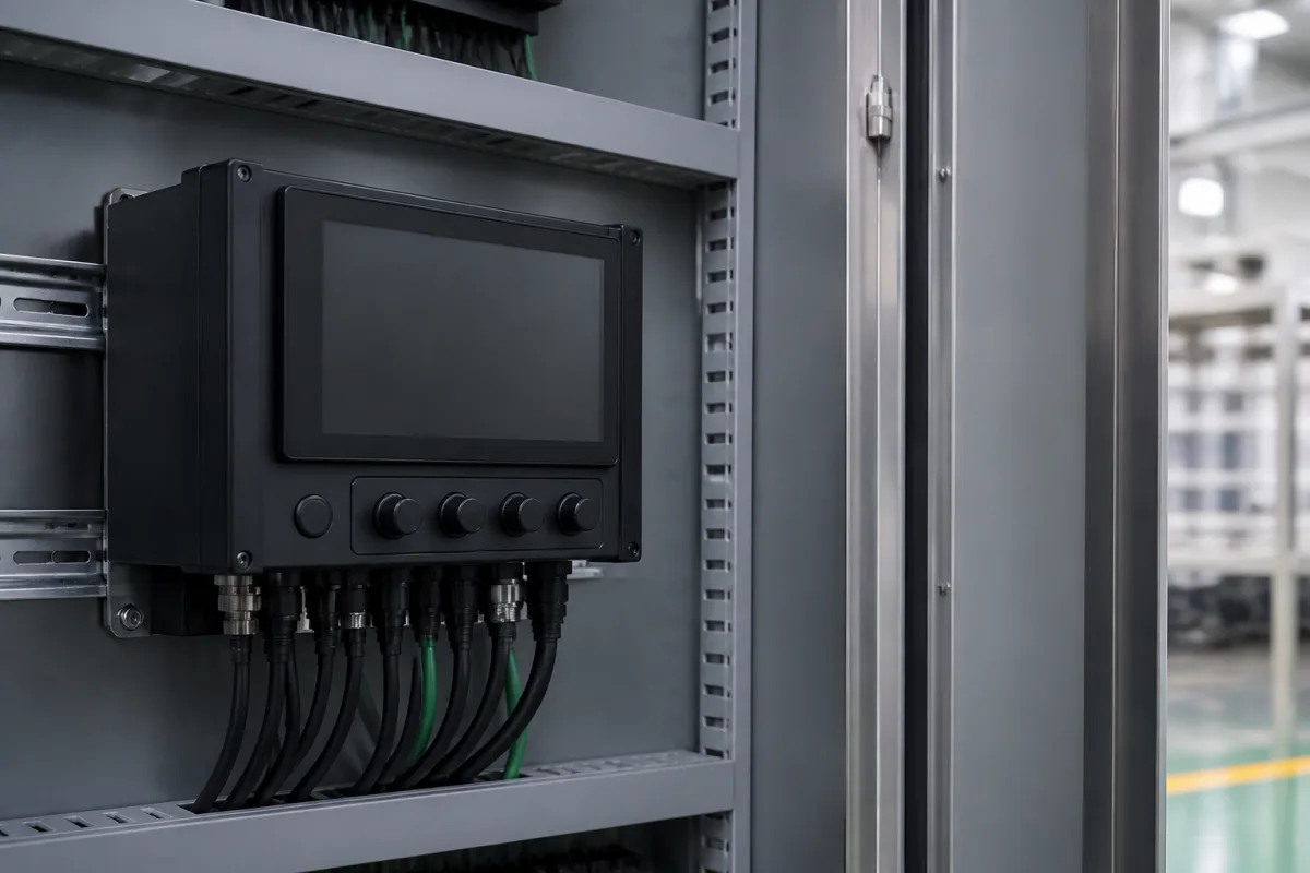
Intelligent controller (power factor controller that measures cos φ and switches the capacitor steps of an automatic bank)
Power factor controllers that run automatic capacitor banks · CT position and phase-angle setting, one or three CTs, sequential, loop and intelligent switching, relay or transistor outputs, auto-initialisation, alarm relay and capacitor monitoring
In an automatic power factor correction bank the controller is the only part that thinks: it reads current and voltage, works out cos φ, and switches capacitor steps through contactors or thyristor modules to hold a target. Specify how it measures, how it chooses and times steps, what outputs it drives and what it reports when something is wrong.
Power factor (reactive power) controllers for automatic low-voltage capacitor banks, with relay outputs for contactor-switched steps or transistor outputs for thyristor-switched steps: measurement wiring, control modes, step timing, alarms and monitoring. The capacitor bank and its sizing are covered on the Capacitor bank for power factor correction page; cabinet cooling, discharge and re-switching delays on the Power capacitor bank cabinet page; step contactors on the Contactors for capacitor bank switching page; active filters on the Active power filter page.
CNFX editorial research · Sources checked October 12, 2026 · 3 sources
Wiring the measurement: CT position, phase angle and one or three CTs
TDK's BR6000 manual sets two wiring rules. The current transformer must carry the load current and "The outputs of the compensation network must be installed behind the current converter (in the direction of current flow)." The controller must also be told the phase angle between the measured current and voltage: its preset table runs from 0° for current in L1 with voltage L1-N, through 90° for current L1 with voltage L3-L2, to 330°, with reversed CT terminals (k↔l) giving the other half of the circle. Where two feeders are summed, the overall ratio is entered, for example two 1000/5 A CTs on a 5 A + 5 A / 5 A summing CT give 2000/5 A. [1]
Circutor's Computer SMART III can measure with three current transformers as well as the usual single CT; Circutor says three-CT measurement "guarantees an analogue reading of the company meter" and suggests changing from one to three CTs when penalties or consumption habits change or the system is significantly unbalanced. It measures 20-300 V phase-neutral or 35-520 V phase-phase and 1-120% of a 5 A or 1 A CT. [3]
Before commissioning, write down which phase the CT is on, which voltage the controller measures, the CT ratio (or summed ratio) and the resulting phase-angle setting.
02
Choosing and timing the steps
The BR6000 has four control modes. Sequential connection switches steps last in, first out, with a long settling time and heavy use of the small stages. Loop connection works first in, first out so equal stages share the wear. The default intelligent loop connection combines loop switching with faster settling through "the simultaneous switching of several or larger capacitor groups as a function of the missing power factor". Combined de-tuning switches two adjoining equal steps that share one choke. [1]
Editorial calculation from those defaults: with a 25 kvar first stage, the controller may switch up to 4 × 25 = 100 kvar in one step. [1]
The output type follows the switching device. EPCOS lists the BR6000-R with 6 or 12 relay outputs "for conventional PFC-systems with slow changing loads" and the BR6000-T with 6 transistor outputs "for dynamic PFC- systems with fast changing loads". [2] Circutor's SMART III 6 has 8 relay outputs (6 steps, 1 fan, 1 alarm) rated 2500 VA maximum switching, plus 2 NPN transistor outputs, and accepts up to four target cos φ for different time periods. [3]
Re-switching delays have to match capacitor discharge; that setting is covered on the Power capacitor bank cabinet page.
03
Auto-initialisation, alarms and capacitor monitoring
BR6000's AUTO-INIT asks for the CT ratio or the first stage if known, then runs "3 test-runs" in which all stages switch on and off to collect and store the system parameters; "Under certain circumstances 3 additional test-runs may be required". If neither value is entered, current and output can only be shown as percent. [1]
Its alarm contact "is closed in normal operation and opens in the event of a fault", with messages for under- and over-compensation, overcurrent, measuring voltage, overtemperature, overvoltage, undervoltage and harmonics; the power of each capacitor is monitored and a defective or deviating capacitor is shown inverted on the display. [1]
Circutor adds residual leakage current measurement with WG-series transformers (10 mA minimum, 0.01-1.5 A range) and capacitor-status tests, with RS-485 Modbus RTU communication. [3]
04
Power factor controller order details
Paste it into your enquiry below or into an email to a maker, then replace every bracket.
Bank: [steps; kvar per step; detuned or not]
Switching: [contactors (relay outputs) or thyristors (transistor outputs)]
Measurement: [CT ratio; 1 or 3 CTs; measured voltage; phase angle]
Voltages: [supply; measuring]
Target: [cos φ; tariff periods]
Timing: [switch-in; switch-off; discharge]
Alarms: [relay; THD; temperature; leakage]
Communication: [RS-485; Modbus]
Mounting: [panel cut-out; DIN rail]
1 company lists this product among what they make. Company figures are quoted from each
company's own website; every card states where the relationship came from.
CNBYG
Manufacturing site to be confirmed for the order
Lists an Intelligent Controller Series including BY83 intelligent capacitor controllers, JKW series automatic reactive power compensation controllers and BY75 reactive power compensation controllers.
Explore company information and manufacturing capabilities, then discuss the scope of your project with a relevant supplier.
Share this page
Compiled and source-reviewed by the CNFX editorial team.
Each manufacturer above links to the page on that company's own website where the product is listed, with the date we checked it. How we source and review
· Page last updated 13 October 2026
Buyer questions
Where must the CT be?
TDK's BR6000 manual says the CT must carry the load current with the capacitor bank connected behind it in the direction of current flow. [1]
Relay or transistor outputs?
Relay outputs drive contactor-switched banks for slow-changing loads; transistor outputs drive thyristor-switched banks for fast-changing loads. [2]
Why use three CTs?
Circutor says three-CT measurement on its SMART III matches the utility meter reading and suits unbalanced systems. [3]
What does auto-initialisation do?
On the BR6000 it switches all stages in three test runs, or six in some cases, and stores the system parameters. [1]
Sources and what still needs a direct check
Sources checked 2026-10-12. TDK (EPCOS) publishes the BR6000 user manual and an application note on its PF controller range; Circutor publishes the Computer SMART III product page.