Editorial Technical Reference

Inverter

This page explains how Inverter is classified within Electrical Equipment Manufacturing. Technical values and manufacturer relationships are research references; confirm the current specification and supplier evidence for each order.

Technical Definition & Core Assembly

Electronic device that converts DC power to AC power with variable frequency and voltage
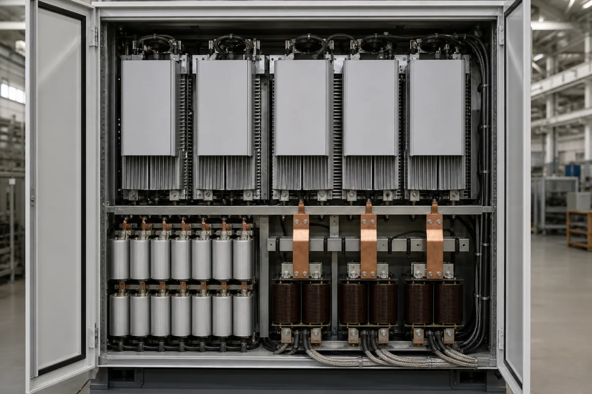
Representative product image. Confirm appearance and specifications with the manufacturer.

Product Specifications

Technical details and manufacturing context for Inverter

Definition
An inverter is a component used in motor drive systems and power conversion applications. It converts direct current (DC) from a power source, such as a battery bank or photovoltaic array, into alternating current (AC) with adjustable frequency and voltage. This enables precise control of motor speed, torque, and direction in industrial processes. The inverter is part of a larger system and must be selected based on load requirements and input source characteristics. Typical parameters include rated power from 1 to 500 kW, input voltage from 200 to 1000 V DC, and output voltage of 220/380 V AC (single-phase or three-phase) at 50/60 Hz, referencing IEC 60038. Efficiency ranges from 95% to 98% at nominal load per IEC 61683, and total harmonic distortion (THD) is below 3% per IEC 61000-3-2. Operating temperature is -20°C to 50°C with derating above 40°C, storage temperature -40°C to 70°C, and relative humidity 0% to 95% non-condensing, per IEC 60068-2 series. Ingress protection ratings vary from IP20 to IP65 (IEC 60529), and cooling methods include forced air (AF) or natural convection (AN) per IEC 60034-6. Weight ranges from 5 to 200 kg, and dimensions vary from 300×500×200 mm to 800×1200×400 mm. These values are reference ranges; actual specifications must be confirmed with the manufacturer for the specific model and application. The inverter operates using power semiconductor devices in a bridge configuration to produce a pulse-width modulated (PWM) waveform. It is essential to verify model-specific parameters, standards compliance, and installation requirements with the legal manufacturer or supplier before procurement.
Working Principle
The inverter uses power semiconductor devices, typically IGBTs or MOSFETs, arranged in a bridge configuration. These switches rapidly turn the DC input on and off, creating a pulse-width modulated (PWM) waveform. By varying the switching frequency and duty cycle, the inverter produces an output that approximates a sinusoidal AC waveform with the desired frequency and voltage. The control electronics adjust the PWM pattern based on feedback from the motor or load, enabling precise speed and torque control. The output is filtered to reduce harmonics, achieving low THD. The inverter also includes protection features such as overcurrent, overvoltage, and thermal shutdown, which are critical for safe operation.
Common Materials
Silicon semiconductor wafers, Copper windings, Aluminum heat sinks, Ceramic substrates, Epoxy resin encapsulation
Technical Parameters
ParameterTypical rangeNotes & selection driver
Rated Power1–500 kWSelect based on load demand
Input Voltage200–1000 V DCMatches PV array or battery bank
Output Voltage220/380 V ACThree-phase or single-phaseIEC 60038
Output Frequency50/60 HzGrid frequencyIEC 60038
Efficiency95–98 %Peak efficiency at nominal loadIEC 61683
THD<3 %Total harmonic distortion of output voltageIEC 61000-3-2
Operating Temperature-20–50 °CDerating above 40°CIEC 60068-2
Storage Temperature-40–70 °CNon-operatingIEC 60068-2
Relative Humidity0–95 %Non-condensingIEC 60068-2-78
Ingress ProtectionIP20–IP65Indoor vs outdoor installationIEC 60529
Cooling MethodAF–ANAir forced or natural convectionIEC 60034-6
Weight5–200 kgDepends on power rating
Dimensions (W×H×D)300×500×200–800×1200×400 mmVaries with power

Ranges are indicative industry figures for RFQ preparation, not a supplier commitment. Confirm every value and standard with the legal manufacturer before ordering.

Components / BOM
  • DC Bus Capacitor Part
    Filters and stores DC input power, smoothing voltage ripple
    Material: Aluminum electrolytic or film capacitors
  • IGBT Module
    Power switching devices that convert DC to AC through high-frequency switching
    Material: Silicon semiconductor with copper terminals
  • Control Board
    Microprocessor-based controller that generates PWM signals and implements control algorithms
    Material: FR4 PCB with copper traces and electronic components
  • Heat Sink Part
    Dissipates heat generated by power semiconductors to maintain operating temperature
    Material: Aluminum alloy with finned design
  • Gate Driver Circuit
    Amplifies control signals to drive IGBT gates with proper voltage and timing
    Material: PCB with optocouplers and driver ICs
  • Output Filter
    Smooths the PWM output so the motor sees something close to a sine wave.
  • Protection Circuit
    Trips on overcurrent, overvoltage or overtemperature before the power devices are destroyed.

Applied To / Applications

This component is essential for the following industrial systems and equipment:

Industrial Ecosystem & Supply Chain Structure

Complementary Systems
Downstream Applications
Specialized Tooling

Application Fit & Sizing Matrix

Operational Limits
pressure: Atmospheric (non-pressurized enclosure)
other spec: Humidity: 5-95% non-condensing, Altitude: ≤1000m without derating
temperature: -10°C to +50°C (operating), -20°C to +70°C (storage)
Media Compatibility
✓ Indoor electrical rooms ✓ Motor control centers ✓ Clean manufacturing environments
Unsuitable: Explosive atmospheres (ATEX Zone 0/1) without proper certification
Sizing Data Required
  • Input DC voltage/current rating
  • Output AC power/load characteristics
  • Required switching frequency/control method

Reliability & Engineering Risk Analysis

Failure Mode & Root Cause
Capacitor degradation
Cause: Electrolytic capacitor drying out due to high operating temperatures, voltage stress, or prolonged use, leading to reduced capacitance, increased ESR, and eventual short/open circuit failures.
IGBT/transistor failure
Cause: Thermal cycling causing solder joint fatigue, overcurrent/overvoltage events (e.g., from motor surges or grid transients), or gate driver circuit faults leading to short-circuit or open-circuit failures in power semiconductors.
Maintenance Indicators
  • Audible high-pitched whine or buzzing from the inverter enclosure, indicating capacitor issues or loose components
  • Visible discoloration, bulging, or leaking from electrolytic capacitors on the DC bus or control boards
Engineering Tips
  • Maintain clean, unobstructed airflow and ensure ambient temperatures stay within manufacturer specifications (typically below 40°C) to reduce thermal stress on capacitors and semiconductors
  • Implement regular infrared thermography inspections of power components and connections to detect abnormal heating before catastrophic failure

Indicative industry ranges for design and RFQ preparation. Confirm the exact figures and applicable standard with the manufacturer before specifying.

Compliance & Manufacturing Standards

Applicable Standards
IEC 62109-1:2010 - Safety of power converters for use in photovoltaic power systems UL 1741 - Standard for Inverters, Converters, Controllers and Interconnection System Equipment for Use With Distributed Energy Resources

Quoted from the published standard.

Manufacturing Precision
  • Output Voltage Accuracy: +/- 2% of rated voltage
  • Frequency Stability: +/- 0.5 Hz
Quality Inspection
  • Harmonic Distortion Test (THD < 5%)
  • Dielectric Withstand Test (Hi-Pot Test)

Manufacturers of Inverter

Manufacturer profiles associated with Inverter.

Sourcing Inverter from China?
Tell us your specification and target quantity — we will match it against manufacturer records and come back with the factories that fit.
Request manufacturers We manufacture this

Manufacturer listings support early research and capability understanding. They are not certification, ranking, or transaction guarantees.

Technical documentation
Request current drawings, revision history, and a signed specification sheet.
Manufacturing capability
Verify equipment lists, process limits, capacity, and representative production evidence.
Inspection readiness
Confirm test methods, calibrated equipment, sampling plans, and traceable reports.
Supplier transparency
Check the legal entity, factory address, ownership, certifications, and direct contacts.

CNFX does not score or rank suppliers. Buyers must verify all claims and documents with the legal manufacturer before ordering.

Supply Chain Compatible Machinery & Devices

Motor Terminal Block

A motor terminal block is a standardized electrical component that provides secure, insulated connection points for motor winding leads.

Explore Specs →
PLC Control System

A digital industrial computer control system that monitors inputs, makes decisions based on a custom program, and controls outputs to automate industrial processes.

Explore Specs →
Control Panel

A centralized interface for monitoring and controlling industrial equipment and processes

Explore Specs →
PLC Control Panel

A centralized interface unit housing the programmable logic controller and associated control components for industrial automation systems.

Explore Specs →

Frequently Asked Questions

What is the primary function of an inverter?

An inverter converts direct current (DC) into alternating current (AC) with adjustable frequency and voltage, enabling control of motor speed and torque in industrial applications.

What parameters should be considered when selecting an inverter?

Key parameters include rated power, input voltage, output voltage and frequency, efficiency, THD, operating temperature, ingress protection, cooling method, weight, and dimensions. These must match the load and power source requirements.

What standards are relevant for inverters?

Relevant standards include IEC 60038 for voltage and frequency, IEC 61683 for efficiency, IEC 61000-3-2 for harmonic distortion, IEC 60068-2 for environmental testing, IEC 60529 for ingress protection, and IEC 60034-6 for cooling methods. Compliance should be verified with the manufacturer.

How does an inverter achieve variable frequency and voltage?

It uses pulse-width modulation (PWM) with power semiconductor switches (IGBTs or MOSFETs) to rapidly switch the DC input, creating an AC waveform. The switching frequency and duty cycle determine the output frequency and voltage.

Data Basis

Editorial classification, named public sources where available, and source-reviewed manufacturer records.

Preliminary Technical Classification
This page supports structured research, RFQ preparation, and supplier evaluation. It does not replace buyer-led supplier qualification, standards review, or technical approval.
Buyer enquiry

Request manufacturing insight for Inverter

Ask for use case, specification boundaries, supplier type, and RFQ preparation information for this product.

Where it goes
Straight to the CNFX editorial desk, and to the manufacturer if this product is linked to a claimed profile. Nothing is broadcast to a supplier list.
Your details stay here
We do not sell or rent enquiry data, and we do not add you to a mailing list. Used only to answer this request.
No commission, no middleman
CNFX is a directory. We take no cut of any order and never negotiate on a supplier's behalf.
What we don't claim
A listing is not an endorsement. Qualify every supplier and verify every figure yourself before ordering.

Your business information is used only to process this request.

Thank you! Your message has been sent. We'll respond within 1–3 business days.
Sorry, we couldn't send your message. Please try again, or email us at contact@cnfx.com.

Need to Manufacture Inverter?

Compare manufacturer profiles with relevant product and process capability.

Previous Product
Wire Tensioning System
Last Product
Get QuotesChat