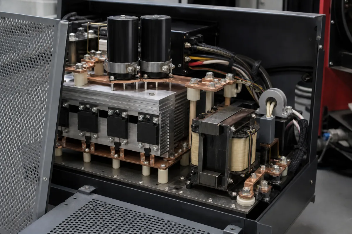
Welding inverter module: the IGBT full-bridge and high-frequency transformer stage of an inverter welding machine
The IGBT inverter stage inside an inverter welding machine · full-bridge switches at 10–40 kHz, high-frequency transformer, output rectifier, and the choice between 34 mm modules and discrete IGBTs
A welding inverter module is the power conversion stage inside an inverter arc welding machine: an input rectifier and DC-link capacitors, an IGBT bridge that chops the DC bus into a high-frequency square wave, a high-frequency transformer that isolates and steps the voltage down, and a secondary rectifier that delivers the welding current. Its switching frequency, semiconductor package and heatsink design set how small, efficient and hot-running the welder is.
The inverter power stage of arc welding machines: IGBT full-bridge, half-bridge or forward converters with their high-frequency transformer, rectifiers and heatsinks, built from IGBT modules or discrete IGBTs. Complete welding power sources with their rated output, open-circuit voltage and installation rules are covered on the Welding power source page; IGBT modules as general-purpose components are covered on the IGBT module page.
CNFX editorial research · Sources checked October 12, 2026 · 3 sources
Rectify, chop the DC bus in an IGBT full bridge at 10–40 kHz, then transform down
Jasic's utility model for an IGBT inverter arc welder describes the main circuit as converting a 50 Hz mains supply to DC in a rectifier, inverting it to high-frequency AC, and rectifying it again for welding; its inversion circuit is a full bridge in which IGBTs G1, G3 and G2, G4 form the bridge arms that turn the DC into a high-frequency square wave for the high-frequency transformer. [3]
Infineon names two-transistor forward, half-bridge, full-bridge and LLC resonant converters as the topologies in medium-power welding machines, controlled by current-mode PWM and switching at zero current on turn-on and hard on turn-off, or fully soft in the LLC case. [1] Its 400 A reference design is a three-phase full-bridge converter with these ratings:
Parameter (Infineon 400 A design)
Value
Input
3-phase 380 V AC ±15%, 50/60 Hz; 25.7 kVA
Output
40–400 A DC; 36 V DC at 400 A
Duty cycle
60% at 400 A (10 min, 40 °C ambient)
Efficiency
80%
Switching frequency
10 to 40 kHz (tested at 20 kHz)
Ambient
−10 to +40 °C
Editorial calculation: 400 A × 36 V = 14.4 kW out; at 80% efficiency about 18 kW is drawn, against the 25.7 kVA input rating, which implies an input power factor near 0.7 at full load.
02
Choose 1200 V IGBT modules or discrete IGBTs by current, frequency and heatsink
Infineon's survey of arc welders lists "mainly discrete devices" for compact machines under 200 A, "discrete and mainly modules" for light to medium industrial machines from 200 A, and modules and discs for heavy machines above 400 A; it adds that for machines of 250 A and more, “the state-of-the-art welding converter designs mainly use IGBT modules such as standard 34 mm modules or even larger packages.” [1]
The first two rows are Infineon's comparison table; Infineon names the discrete as IKQ75N120CS6 in its design specification and IKY75N120CS6 in its comparison, so confirm the exact part with the supplier. [1] The third row is from Semikron's datasheet, which lists "electronic welders at fsw up to 20 kHz" among typical applications and gives 4,000 V AC isolation for 1 minute. [2] Switching energies were measured under each maker's own test conditions and cannot be compared directly.
Editorial calculation, an upper bound at Semikron's hard-switched test point (600 V, 75 A, 150 °C) rather than a welder's operating loss: (11 + 6.9) mJ × 20,000 switchings per second ≈ 358 W per IGBT. Infineon notes that zero-current switching at turn-on, used in these converters, enables higher switching frequencies and better efficiency. [2][1]
Device (75 A, 1200 V)
VCE(sat) at 75 A
Eon / Eoff
Tj max
Rth(j-c) per IGBT
Weight
Original module in a 400 A welder (per Infineon)
3.10 V (25 °C), 3.45 V (125 °C)
5.82 / 3.44 mJ at 125 °C
150 °C
0.19 K/W
150 g
Infineon IKY75N120CS6 TO-247PLUS discrete
1.85 V (25 °C), 2.15 V (125 °C)
3.3 / 5.3 mJ at 175 °C
175 °C
0.17 K/W
6 g
Semikron SKM75GB12T4 SEMITRANS 2 half-bridge
1.85 V (25 °C), 2.25 V (150 °C)
11 / 6.9 mJ at 150 °C, 600 V
175 °C (operate −40 to +150 °C)
0.38 K/W
—
03
Mount discretes on the heatsink with or without insulation
Modules are isolated from the heatsink; discrete IGBTs need insulating material unless the design mounts them directly on electrically separated heatsinks, as Infineon's 400 A design does. [1]
Infineon measured the junction-to-heatsink thermal resistance of a TO-247PLUS IGBT, M4 screw at 1 Nm with a 119 N clip, on a forced-cooled heatsink: 0.73 to 0.82 K/W with thermal grease and Al₂O₃ insulation, and 0.59 to 0.60 K/W with grease only. At about 68 W the junction-to-heatsink rise was 56 °C with insulation and 41.5 °C without. [1]
In the 400 A design the discrete IGBTs reached a body case temperature of 90 °C at 25 °C ambient, and in an existing 400 A welder converted from two 34 mm 75 A half-bridge modules to discretes (still insulated) the heatsink ran 3 °C cooler than with the original modules; simulation put the uninsulated discrete solution about 27 °C lower in junction temperature than the module solution. [1]
For a replacement or new design, give the welder's rated current and duty cycle, DC bus voltage, switching frequency, topology, and the heatsink and fan arrangement, and ask for the IGBT part numbers and their thermal resistance as mounted.
04
Data for a welding inverter module enquiry
Paste it into your enquiry below or into an email to a maker, then replace every bracket.
Welder: [process; rated output current and voltage; duty cycle at 40 °C]
Supply: [single or three phase; voltage range]
Topology: [full bridge, half bridge, two-transistor forward, LLC]
Switching: [frequency; soft or hard switching]
Devices: [IGBT module type or discrete part; voltage and current rating]
Transformer: [turns ratio; core; frequency]
Cooling: [heatsink; fan; insulation method]
Spare part: [original part number; connector and mounting]
Explore company information and manufacturing capabilities, then discuss the scope of your project with a relevant supplier.
Share this page
Compiled and source-reviewed by the CNFX editorial team.
Each manufacturer above links to the page on that company's own website where the product is listed, with the date we checked it. How we source and review
· Page last updated 13 October 2026
Buyer questions
At what frequency does a welding inverter switch?
Infineon's 400 A full-bridge reference design runs at 10 to 40 kHz and was tested at 20 kHz; Semikron rates its SKM75GB12T4 module for electronic welders at switching frequencies up to 20 kHz. [1][2]
Are welding inverters built with IGBT modules or discrete IGBTs?
Both. Infineon's table gives “Mainly discrete devices” under 200 A, “Discrete and mainly modules” from 200 A, and “Modules and discs” above 400 A. [1]
Why mount discrete IGBTs without insulation?
Infineon measured junction-to-heatsink resistance falling from about 0.82 to 0.60 K/W when the Al₂O₃ insulation was left out, about 25% lower. [1]
Sources and what still needs a direct check
Sources checked 2026-10-12. Design and device data come from Infineon's application note AN2019-10 and Semikron's SKM75GB12T4 datasheet; the circuit description from Jasic's German utility model DE 20 2009 008 641 U1.