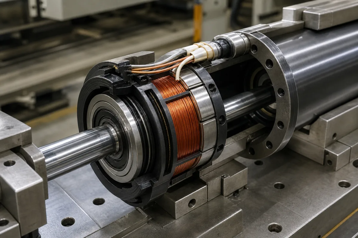
Electromagnetic coil for magnetorheological (MR) dampers (piston and rotary field coils)
Field coil wound on the piston or housing of a magnetorheological damper · ampere-turns against steel saturation, wire gauge, layers and spools, magnet wire thermal class, inductance and L/R response, a rotary damper coil example
The electromagnetic coil of a magnetorheological (MR) damper is a winding of insulated magnet wire on the damper's piston (in a linear damper) or around its housing or rotor (in a rotary damper or brake). Current through it drives magnetic flux across the narrow gap filled with MR fluid, and the fluid's yield stress, and with it the damping force, rises with the flux. The coil's turns, wire gauge and layers decide how much current and power the damper needs, how hot it runs and how fast its force follows the control signal. Settle three things first: the ampere-turns the magnetic circuit needs without saturating the steel, the wire gauge and winding geometry that fit the piston at the supply voltage, and the inductance-to-resistance time constant the control loop can accept.
Field coils (magnet-wire windings with bobbins, lead-outs and potting) for linear and rotary magnetorheological dampers, brakes and clutches: ampere-turns and magnetic circuit, wire gauge and winding geometry, insulation thermal class, resistance, inductance and response. Complete MR damper units with fluid, accumulator and force curves are covered on the Magnetorheological damper page; coils of on-off valves on the Solenoid valve page; mould stirrer coils on the Mould electromagnetic stirrer (M-EMS) coil assembly page. Push-pull solenoid actuators and relay coils are outside this page.
CNFX editorial research · Sources checked October 12, 2026 · 3 sources
Ampere-turns for the gap flux while keeping the steel below 1.5 T
Gavin, Hoagg and Dobossy at Duke University describe an MR damper whose piston is wrapped in magnet wire, generating flux in the piston, cylinder and fluid; at intense fields (1 T) the fluid's yield stress rises from below 0.1 kPa to roughly 100 kPa, enough to raise damping force by a factor of ten or more. They model yield stress as proportional to gap flux density with a constant of about 80 kPa/T. [1]
The current needed comes from a magnetic Kirchhoff law: the turns N times the current i equal the sum of field strength times path length around the circuit (gap, poles, core and cylinder wall). The authors bounded the flux density in the steel core and wall at 1.5 T so that no part saturates, noting that lower flux also reduces remanent magnetisation. [1] Editorial calculation: with their 80 kPa/T constant, a gap flux of 0.5 T gives about 0.5 × 80 = 40 kPa of yield stress, half of what 1 T gives.
Their design constraints for the damper included a coil voltage below 24 V, a time constant below 0.10 s, a total coil length of the spools and poles below 0.25 m, and a current below the wire's rating, inside a commercial hydraulic cylinder of 46.228 mm outer diameter with a 15.875 mm rod. [1]
Give the coil maker the piston or housing drawing with the winding space, the required ampere-turns or gap flux, the supply voltage and maximum current, the duty cycle, the fluid temperature range and how leads leave the piston (through the rod or a fitting).
02
Wire gauge, layers and spools: why the Duke design settled on 20-gauge wire, 4 spools and 4 layers
The Duke study searched seven wire gauges from 16 to 28, with the number of layers limited by the piston diameter and the number of spools by the piston length, and computed an optimum for every combination. The optimum used 20-gauge wire with 4 spools and 4 layers and needed 60 W; there were no feasible designs with wire smaller than 22 gauge and few with more than 4 or fewer than 2 layers. [1]
Resistance follows from wire length: R = r × N × π × Dc × Ns, with r the resistance per unit length, N the turns per spool, Dc the core diameter and Ns the number of spools. In the sensitivity analysis a ±28% change in turns, but only ±7% in gap flux, raised the objective by 10%. [1]
Conwire lists heavy-build round copper magnet wire of thermal class 200 °C to NEMA MW 35-C/73-C and IEC 60317-13, with clear polyester overcoated with polyamide-imide, at a nominal overall diameter of 0.0346 in for 20 AWG. [3] Editorial calculation: 0.0346 in ≈ 0.88 mm, so four layers of that wire build about 3.5 mm radially before any allowance for nesting, bobbin or potting, which is the depth the piston groove must provide.
03
Inductance and the L/R time constant: how quickly damper force follows the current
In the Duke analysis the coil's inductance is L = Ns × N × flux ÷ i and the inductive time constant is T = L ÷ R; the design objective minimised the time constant together with electrical power. The built damper produced a maximum of 4 kN at 10 A and about 0.30 kN with the coil off; switched on, its force rose by a factor of ten in under 50 ms, and switched off it returned to low force in less than 20 ms. [1]
The paper's comparison table lists, for an MR device with MRF-240BS fluid at 1 T, a coil inductance of 0.015 to 0.5 H, a response time of 0.1 to 12 ms, a flow gap of 0.8 to 2.8 mm and a power supply of 4 to 24 V continuous with 200 V peak. [1] Editorial note: a supply that can briefly apply more than the steady-state voltage drives current into an inductive coil faster than its L/R time constant alone allows; ask the coil maker for measured inductance and resistance so the driver can be matched.
04
A rotary MR damper coil: 0.6 mm wire, 800–1,000 turns, 6 Ω at 2 A
A University of Science and Technology of China patent, CN 1189679 C, gives an example rotary MR damper 116 mm in outer diameter and 70 mm high whose electromagnetic coil is wound from 0.6 mm enamelled wire, 800 to 1,000 turns, with a 40 mm inner diameter and 6 Ω resistance, for a maximum working current of 2 A and maximum input power of 24 W; it uses LORD MR fluid. [2]
The patent reports damping torque of 0.6 N·m at zero field and 30 N·m at maximum current, and a field below 0.6 mT on the device's outer surface at 2 A excitation. [2] Editorial calculation: 2 A × 6 Ω = 12 V and 2² × 6 = 24 W, matching the stated maximum input power; 800–1,000 turns at 2 A give 1,600–2,000 ampere-turns; 30 ÷ 0.6 = a 50-fold torque range.
The patent also notes that stacking more damping discs lengthens the device and needs more coil current to keep the field strength, making heat harder to dissipate, which is why its design uses a single disc. [2]
05
Send the magnetic circuit, the winding space and the driver limits
Paste it into your enquiry below or into an email to a maker, then replace every bracket.
Device: [linear piston or rotary; drawing of winding space]
Magnetic target: [gap flux or ampere-turns; steel grade]
Electrical: [supply voltage; maximum current; duty cycle; driver type]
Wire: [gauge; insulation build; thermal class]
Winding: [spools; layers; turns; resistance and tolerance; inductance]
Environment: [fluid temperature range; immersion in MR fluid; potting]
Leads: [exit route; connector; sealing]
Explore company information and manufacturing capabilities, then discuss the scope of your project with a relevant supplier.
Share this page
Compiled and source-reviewed by the CNFX editorial team.
Each manufacturer above links to the page on that company's own website where the product is listed, with the date we checked it. How we source and review
· Page last updated 13 October 2026
Buyer questions
Why limit flux in the steel of an MR damper to 1.5 T?
In the Duke design study, keeping core and wall flux below 1.5 T avoids saturation, so extra current still raises gap flux, and lowers remanent magnetisation. [1]
What wire is used for MR damper coils?
The Duke optimum used 20-gauge magnet wire in 4 spools of 4 layers; the USTC rotary damper uses 0.6 mm enamelled wire, 800–1,000 turns, 6 Ω. [1][2]
How fast does an MR damper respond to coil current?
The Duke damper's force rose tenfold in under 50 ms and fell in under 20 ms; response is limited by the coil's L/R time constant. [1]
Sources and what still needs a direct check
Sources checked 2026-10-12. The Duke paper reports a university design study and test of one MR damper; the USTC patent describes its applicant's rotary damper; Conwire lists the magnet wire it sells. Values apply to those devices and products.