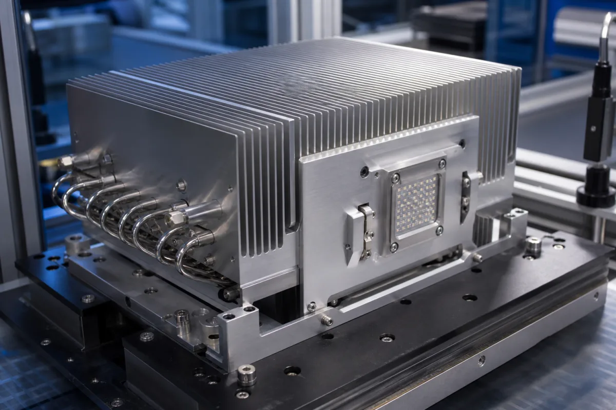
Heat-pipe heat sink assembly for high-power COB LED modules
Heat-pipe cooling assemblies for high-power COB LED light engines · machined LED plate, copper heat pipes and fin stack, sized by pipe diameter, length, orientation and a case-temperature test
A precision heat sink assembly for a high-power COB LED light engine is built from separate parts rather than one extrusion: a machined plate that the LED array or its holder is screwed to, copper heat pipes pressed, soldered or clamped into that plate, and a fin stack where the heat is finally given to the air. The heat pipes carry the heat but do not dissipate it, so the assembly is sized twice: once for what the pipes can carry over their length and orientation, and once for the fin area that releases the heat to the room.
Assembled LED cooling modules that combine a machined aluminium or copper mounting plate for a COB LED array, copper heat pipes and a fin stack, for luminaires such as high bays, floodlights and stage lighting. General aluminium heat sink selection by process and thermal resistance is covered on the Aluminium heat sink page; extruded profiles sold by length on the Aluminum extruded heat sink profile page; heat sinks for IGBT power modules on the Industrial aluminium heat sink for IGBT power modules page; and water-cooled rectifier heat sinks on the Rectifier heat sink and cooling system page.
CNFX editorial research · Sources checked October 12, 2026 · 3 sources
What each heat pipe can carry: 3–12 mm diameter, 70–150 mm length and the pull of gravity
In this assembly the heat pipe count and diameter decide whether the heat reaches the fins at all. Wakefield Thermal's selection guide shows that capacity falls steeply with pipe length.
Values from Wakefield Thermal's heat carrying capacity table for round, unflattened heat pipes. [1] Wakefield adds that its round pipes are rated from −40 °C to 150 °C with 130 °C recommended as the maximum for continuous use, and that the phase-change benefit does not begin until about 10 °C. [1]
Orientation matters in a luminaire that may hang with the LED facing down: Wakefield reports that gravity can nearly double capacity when the heat source is below the condenser and cut it in half in the opposite direction, compared with a horizontal pipe, with the effect nearly zero for short pipes of 3–4 inches. It limits grooved-wick pipes above 15° out of horizontal and mesh-wick pipes to 30°, while sintered powder-wick pipes can be used horizontally, vertically and upside down. [1]
Bending and flattening to fit the plate also cost capacity: Wakefield gives a bend radius of 3–5 times the pipe diameter depending on diameter and method, warns that over-bending can collapse the pipe, says flattening reduces capacity as if a smaller pipe were used (more so for larger starting diameters), and quotes a tolerance of ±0.4 mm on flattened dimensions. Pipes can be soldered or epoxied into grooves in the plate, or clamped between grooved plates with thermal grease. [1]
Cree LED lists heat pipes for thermal loads under 140 W in its comparison of active cooling methods, and notes that heat pipes move heat to another location, so a heat sink is still needed there. [2]
Round heat pipe OD
Capacity at 70 mm length
At 100 mm
At 150 mm
3 mm
33 W
23 W
15 W
4 mm
89 W
62 W
41 W
5 mm
144 W
101 W
67 W
6 mm
192 W
134 W
89 W
8 mm
278 W
194 W
129 W
10 mm
289 W
249 W
166 W
12 mm
375 W
318 W
212 W
Give the assembly maker the LED heat load in watts, the luminaire's mounting orientation and tilt range, the space for pipe routing, and ask for capacity of the pipes as bent and flattened, not as straight round pipes.
02
Proving the assembly: LED case temperature, thermocouple position and at least one hour to stabilise
Cree LED's thermal management note sets out how a cooling assembly should be measured before the LED's lifetime claims are relied on. [2]
Cree asks for tests in the real-life worst case, with the same airflow, orientation, ambient and other heat sources such as the power supply, and to wait one hour at the very least for each measurement, watching the difference between the measuring point and ambient rather than the absolute reading. Thermocouples are placed as close to the LED as possible on a metal pad connected to the thermal trace, attached with thermally conductive epoxy or solder, and kept out of the light path. Infrared cameras are useful for hot spots but need the exact emissivity for absolute values. [2]
For first sizing of the fin stack Cree gives 5–20 W/m²K as the range for natural convection, 10 W/m²K as a starting assumption, and roughly 5–10 square inches of heat sink surface per watt of heat; anodising raises an aluminium heat sink's emissivity to about 0.8. [2] Editorial calculation: for 91.5 W of heat, 5–10 in²/W gives about 0.30–0.59 m² of fin surface.
A tested example: researchers at the Lashkaryov Institute of Semiconductor Physics and Igor Sikorsky Kyiv Polytechnic Institute built a compact LED lamp in which 150 mm heat pipes carry heat from the LED matrix to concentric heat-exchanger rings cooled by natural convection. With an LED source power of 140.7 W the modelled LED matrix case temperature was 60.5 °C against 61.3 °C measured; the measured thermal power of the matrix was 91.5 W, the junction temperature 79.6 °C and the total thermal resistance of the cooling system 0.453 °C/W. [3] Editorial calculation: 91.5 W of heat is 65% of the 140.7 W source power.
Measurement
What to agree with the assembly maker
LED case or solder-point temperature
Thermocouple location from the LED maker's handling note; attachment by conductive epoxy or solder. [2]
Stabilisation
At least one hour per reading, recording ambient. [2]
Orientation
Test in the luminaire's worst mounting position, since pipe capacity depends on it. [1][2]
Heat load
Thermal watts, not electrical input; in the Kyiv test 91.5 W of 140.7 W. [3]
03
When a passive heat-pipe assembly is not enough: fan, liquid and other options by heat load
Cree LED's comparison puts rough ceilings on each cooling method for LED systems, with heat pipes at under 140 W. [2]
Cree warns that few active cooling devices match LED lifetimes and that the cooler can become the weakest link, so passive natural-convection designs are preferred where they suffice. [2]
Method
Heat load in Cree's table
Cree's comment
Fan sink
< 40 W
Extra power lowers lm/W; if the fan fails the whole unit must be replaced. [2]
Explore company information and manufacturing capabilities, then discuss the scope of your project with a relevant supplier.
Share this page
Compiled and source-reviewed by the CNFX editorial team.
Each manufacturer above links to the page on that company's own website where the product is listed, with the date we checked it. How we source and review
· Page last updated 13 October 2026
Buyer questions
How much heat can one 6 mm heat pipe carry in an LED cooler?
Wakefield Thermal lists 192 W at 70 mm length, 134 W at 100 mm and 89 W at 150 mm for a round 6 mm pipe; bending, flattening and adverse orientation reduce this. [1]
Does orientation matter for a heat-pipe LED heat sink?
Yes. Wakefield reports gravity can nearly double capacity with the heat source below the condenser and halve it the other way on long pipes; grooved wicks are limited above 15° from horizontal. [1]
How long should an LED heat sink test run before reading temperatures?
Cree LED recommends waiting at least one hour for each thermal measurement and recording the difference between the measuring point and ambient. [2]
Sources and what still needs a direct check
Sources checked 2026-10-12. Wakefield Thermal is a heat pipe and heat sink maker, Cree LED an LED maker writing about cooling its own LEDs, and the Kyiv study is a journal paper testing one heat-pipe LED cooler.