Editorial Technical Reference

Buffing Unit

This page explains how Buffing Unit is classified within Fabricated Metal Product Manufacturing. Technical values and manufacturer relationships are research references; confirm the current specification and supplier evidence for each order.

Technical Definition & Core Assembly

A mechanical component within a finishing line that performs surface polishing operations on metal products.
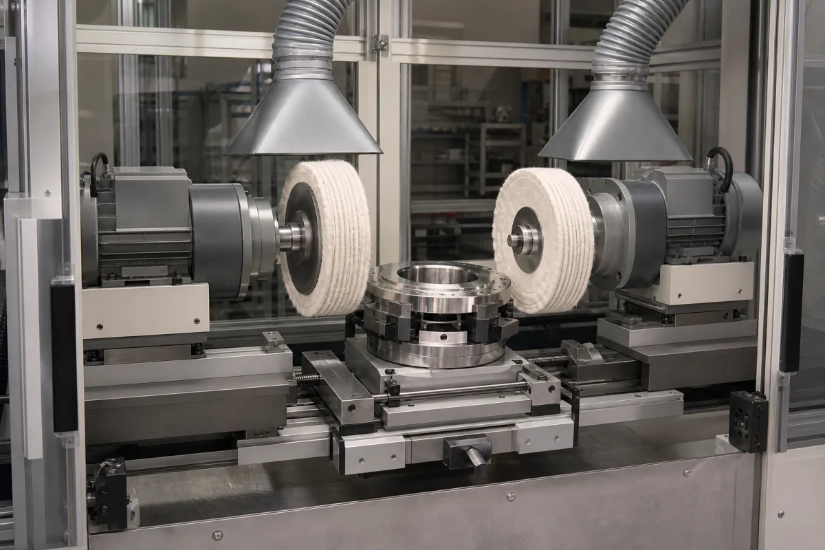
Representative product image. Confirm appearance and specifications with the manufacturer.

Product Specifications

Technical details and manufacturing context for Buffing Unit

Definition
The Buffing Unit is a specialized component integrated into industrial finishing lines, designed to polish and refine the surface of metal workpieces. It typically consists of rotating buffing wheels or belts that apply polishing compounds to achieve desired surface finishes, removing minor imperfections and enhancing aesthetic appearance. This unit is commonly used in the fabricated metal product manufacturing industry, where surface quality is critical for both functional and cosmetic reasons. The unit operates by rotating buffing wheels or belts at controlled speeds while applying polishing compounds to the workpiece surface. The abrasive action of the buffing media, combined with the polishing compound, removes surface irregularities and creates a smooth, reflective finish through mechanical friction. Key parameters include wheel diameter (200–600 mm), spindle speed (1500–3000 rpm), motor power (2.2–7.5 kW), workpiece width capacity (100–800 mm), feed speed (2–15 m/min), achievable surface roughness (Ra 0.2–0.8 µm), spindle runout (≤0.02 mm), operating pressure (0.4–0.6 MPa), air consumption (0.5–2.0 m³/min), electrical supply (380–480 V AC, IEC 60038), noise level (75–85 dB(A), ISO 11201), machine weight (800–2500 kg), and dimensions (1500×1200×1800 mm). Materials commonly processed include steel and aluminum, and polishing compounds are used. The unit is available in various configurations to suit different production requirements. When selecting a buffing unit, it is essential to verify model-specific values and standards with the legal manufacturer or supplier, as the listed parameters are reference ranges that must be confirmed for the actual application. Proper maintenance, including regular inspection of wheels, belts, and spindle runout, is necessary to ensure consistent performance and safety. The unit should be operated within its specified parameters to avoid overheating or excessive wear. Always consult the manufacturer's documentation for installation, operation, and maintenance guidelines.
Working Principle
The buffing unit operates by rotating buffing wheels or belts at controlled speeds while applying polishing compounds to the workpiece surface. The abrasive action of the buffing media, combined with the polishing compound, removes surface irregularities and creates a smooth, reflective finish through mechanical friction. The spindle speed and wheel pressure are adjusted based on the material and desired finish. The workpiece is fed through the unit at a controlled rate to ensure uniform polishing. The process generates heat, so cooling and lubrication may be required. The unit's parameters, such as wheel diameter, spindle speed, and feed speed, must be set according to the specific application to achieve optimal results.
Common Materials
Steel, Aluminum, Polishing Compounds
Technical Parameters
ParameterTypical rangeNotes & selection driver
Wheel Diameter200–600 mmDetermines contact area and surface finish.
Spindle Speed1500–3000 rpmHigher speeds improve finish but increase heat.
Motor Power2.2–7.5 kWSelect based on workpiece hardness and width.
Workpiece Width Capacity100–800 mmMaximum width of workpiece that can be processed.
Feed Speed2–15 m/minAffects throughput and surface quality.
Surface Roughness AchievableRa 0.2–0.8 µmDepends on abrasive grit and feed rate.
Spindle Runout≤0.02 mmCritical for uniform polishing.
Operating Pressure0.4–0.6 MPaPneumatic pressure for wheel contact force.
Air Consumption0.5–2.0 m³/minEnsure adequate compressor capacity.
Electrical Supply380–480 V ACThree-phase, 50/60 Hz.IEC 60038
Noise Level75–85 dB(A)At operator position, may require hearing protection.ISO 11201
Machine Weight800–2500 kgAffects installation and floor loading.
Dimensions (L×W×H)1500×1200×1800 mmTypical footprint; verify for your model.

Ranges are indicative industry figures for RFQ preparation, not a supplier commitment. Confirm every value and standard with the legal manufacturer before ordering.

Components / BOM
  • Buffing Wheel Part
    Primary polishing surface that contacts the workpiece
    Material: Cotton, Felt, or Synthetic Fibers
  • Motor Assembly
    Provides rotational power to the buffing wheels
    Material: Steel, Copper Windings
  • Compound Applicator
    Applies polishing compounds to the buffing surface
    Material: Plastic, Stainless Steel
  • Spindle
    Carries the buffing wheel and transmits rotation from the motor; its speed sets the polishing action.
  • Workpiece Feed Mechanism Optional
    Moves the workpiece past the wheels at the set feed speed so polishing is even; hand-fed units do without it.

Applied To / Applications

This component is essential for the following industrial systems and equipment:

Industrial Ecosystem & Supply Chain Structure

Complementary Systems
Downstream Applications
Specialized Tooling

Application Fit & Sizing Matrix

Operational Limits
pressure: Max 5 bar system pressure
flow rate: 10-100 L/min slurry flow
temperature: 10°C to 50°C (operating range)
slurry concentration: Up to 30% solids by weight
Media Compatibility
✓ Stainless steel components ✓ Aluminum alloys ✓ Copper-based metals
Unsuitable: High-corrosion environments with chlorides or acids
Sizing Data Required
  • Workpiece dimensions (LxWxH)
  • Required surface finish (Ra value)
  • Production throughput (parts/hour)

Reliability & Engineering Risk Analysis

Failure Mode & Root Cause
Abrasive wheel degradation
Cause: Excessive pressure or improper material compatibility leading to rapid abrasive wear and loss of surface finish quality
Bearing seizure in spindle assembly
Cause: Contamination ingress (dust, debris) combined with inadequate lubrication, causing overheating and mechanical failure
Maintenance Indicators
  • Unusual high-pitched whining or grinding noises from spindle area
  • Visible sparking patterns changing from consistent to erratic during operation
Engineering Tips
  • Implement predictive maintenance using vibration analysis on spindle bearings to detect early imbalance or wear
  • Establish strict material compatibility matrix and pressure settings for different workpieces to optimize abrasive wheel life

Indicative industry ranges for design and RFQ preparation. Confirm the exact figures and applicable standard with the manufacturer before specifying.

Compliance & Manufacturing Standards

Applicable Standards
ANSI B11.19 - Performance criteria for safeguarding CE Marking - Machinery Directive 2006/42/EC

Quoted from the published standard.

Manufacturing Precision
  • Bearing bore: +/-0.01mm
  • Surface flatness: 0.05mm
Quality Inspection
  • Vibration analysis for dynamic balance
  • Surface roughness measurement (Ra value)

Manufacturers of Buffing Unit

Manufacturer profiles associated with Buffing Unit.

Sourcing Buffing Unit from China?
Tell us your specification and target quantity — we will match it against manufacturer records and come back with the factories that fit.
Request manufacturers We manufacture this

Manufacturer listings support early research and capability understanding. They are not certification, ranking, or transaction guarantees.

Technical documentation
Request current drawings, revision history, and a signed specification sheet.
Manufacturing capability
Verify equipment lists, process limits, capacity, and representative production evidence.
Inspection readiness
Confirm test methods, calibrated equipment, sampling plans, and traceable reports.
Supplier transparency
Check the legal entity, factory address, ownership, certifications, and direct contacts.

CNFX does not score or rank suppliers. Buyers must verify all claims and documents with the legal manufacturer before ordering.

Supply Chain Compatible Machinery & Devices

Industrial Tube Bending Machine

An industrial tube bending machine is a CNC-controlled device designed to precisely bend metal tubes and pipes to specific angles and radii.

Explore Specs →
Precision Linear Motion Guide Rail

Precision linear guide component for smooth, accurate motion in industrial machinery

Explore Specs →
Precision Aluminum Extrusion Profile

Precision aluminum extrusion profiles are semi-finished structural components produced by forcing heated aluminum alloy through a shaped die.

Explore Specs →
Precision Hydraulic Valve Spool

A precision hydraulic valve spool is a cylindrical metal component that slides within a valve body to regulate hydraulic fluid flow, pressure, and direction.

Explore Specs →

Frequently Asked Questions

What is the typical wheel diameter range for a buffing unit?

The wheel diameter typically ranges from 200 to 600 mm, depending on the model and application. This parameter determines the contact area and surface finish. Always verify the exact specification with the manufacturer for your specific unit.

What spindle speed is recommended for buffing operations?

Spindle speeds typically range from 1500 to 3000 rpm. Higher speeds can improve finish but increase heat generation. The optimal speed depends on the workpiece material and desired surface quality. Consult the manufacturer's guidelines for your specific application.

What materials can be processed with a buffing unit?

Common materials include steel and aluminum. The unit uses polishing compounds to achieve the desired finish. The selection of buffing media and compound depends on the workpiece hardness and required surface roughness. Always confirm compatibility with the manufacturer.

What is the achievable surface roughness with a buffing unit?

The achievable surface roughness is typically in the range of Ra 0.2 to 0.8 µm, depending on the abrasive grit, feed rate, and other parameters. The actual result may vary based on the specific setup and workpiece material. Verify with the manufacturer for your application.

Data Basis

Editorial classification, named public sources where available, and source-reviewed manufacturer records.

Preliminary Technical Classification
This page supports structured research, RFQ preparation, and supplier evaluation. It does not replace buyer-led supplier qualification, standards review, or technical approval.
Buyer enquiry

Request manufacturing insight for Buffing Unit

Ask for use case, specification boundaries, supplier type, and RFQ preparation information for this product.

Where it goes
Straight to the CNFX editorial desk, and to the manufacturer if this product is linked to a claimed profile. Nothing is broadcast to a supplier list.
Your details stay here
We do not sell or rent enquiry data, and we do not add you to a mailing list. Used only to answer this request.
No commission, no middleman
CNFX is a directory. We take no cut of any order and never negotiate on a supplier's behalf.
What we don't claim
A listing is not an endorsement. Qualify every supplier and verify every figure yourself before ordering.

Your business information is used only to process this request.

Thank you! Your message has been sent. We'll respond within 1–3 business days.
Sorry, we couldn't send your message. Please try again, or email us at contact@cnfx.com.

Need to Manufacture Buffing Unit?

Compare manufacturer profiles with relevant product and process capability.

Previous Product
Welding Positioner
Last Product
Get QuotesChat