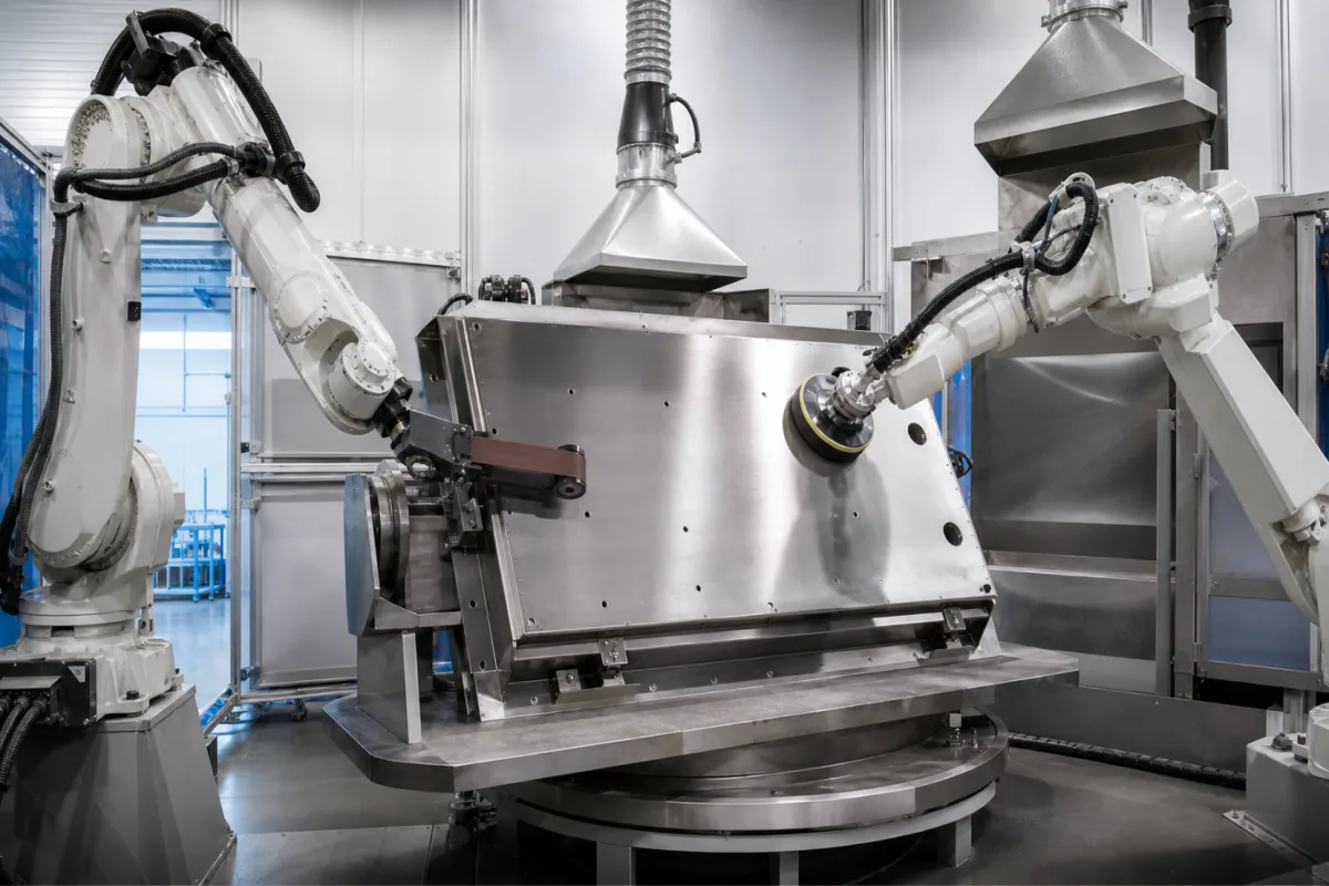
Robotic surface finishing station: force-controlled belt sanding, grinding and polishing of fabricated metal parts
Robot grinding, sanding and polishing cells for fabricated metal parts · contact force held by a compliance flange (100 to 800 N, 11.5 to 98 mm stroke), force raised as the belt wears, and the choice between a belt sander on the arm and a servo belt stand
Manual grinding and polishing depend on the operator's feel for how hard to press. A robotic finishing station replaces that feel with a force-control device between robot and abrasive, a rule for changing the force as the abrasive wears, and a layout that decides whether the robot carries the sander to the part or carries the part to a fixed belt. The pictured cell shows the first layout: two arms, one with a contact-wheel belt sander and one with a disc sander, working a stainless weldment on a turntable under extraction hoods.
Robot cells that grind, belt-sand, deburr and polish formed, cast or welded metal components, with force-compliance devices, robot-mounted belt and disc sanders, servo belt stands for part-in-hand work, and part positioners. Batch anodizing lines for aluminium extrusions are covered on the Aluminum profile anodizing production line page; the extraction hoods and ductwork that serve grinding cells are covered on the Dust extraction hoods and duct network for metal grinding page, and reciprocating-table machines on the Surface grinding machines page.
CNFX editorial research · Sources checked October 13, 2026 · 4 sources
A compliance flange between robot and sander: 100 N to 800 N of contact force over 11.5 mm to 98 mm of stroke
A robot follows a programmed path, but a welded or formed part never matches its drawing exactly. FerRobotics' Active Contact Flange sits between the robot wrist and the tool and, in the maker's words, provides "interactive compensation for surface tolerances up to 100 mm with guaranteed consistent contact force" without changing the robot path; integrated gravity compensation keeps the process force constant as the tool orientation changes. [1]
All models in the 2024 datasheet run on compressed air through a 6 mm line at up to 7 bar, filtered to 30 µm and oil- and water-free to ISO 8573-1 class 3, at +5 to +45 °C ambient; the flange is rated IP65 when fitted with suitable filters and mounts on ISO 9409-1 bolt circles of 50 mm (XS and ACF/110/10) or 80 mm (HD models). Ethernet TCP/IP is standard, with EtherNet/IP, DeviceNet, Profibus, Profinet and Modbus TCP as options. [1]
The XS version is described for small robots and workspaces within 1000 mm, the HD versions for a higher load capacity and removal rate. [1] Editorial note: the stroke has to exceed the deviation between the programmed path and the real part surface, while the force rating has to cover the highest contact force the abrasive needs; the 11.5 mm XS stroke and the 98 mm long-stroke versions are answers to very different part tolerances.
FerRobotics ACF model
Max. force push/pull (N)
Stroke (mm)
Max. overturning moment (N·m)
ACF/111/01 XS
100
11.5
25
ACF/110/10
100
98
40
ACF/111/04 HD
200
35.5
250
ACF/111/05 HD and /10 HD
250
48 and 98
350
ACF/121/05 HD and /10 HD
500
48 and 98
350
ACF/131/05 HD and /10 HD
800
48 and 98
350
Give the heaviest sander or spindle the flange must carry, the force range the abrasive needs, the largest path-to-part deviation expected on a welded part, and the robot flange pattern.
02
Constant removal from a wearing belt: Rolls-Royce raised the force from 75 N to 90 N after about 15 m of toolpath
An abrasive belt removes less metal as its grains dull. Rolls-Royce's patent US10287890B2 compensates by increasing the force between belt and component as the toolpath proceeds, linearly or in steps from a minimum to a maximum force, and notes that removal is inversely proportional to the feed rate, so feed can be used to vary stock removal where the surface needs more or less. [2]
Editorial calculation: 15 N on a 75 N start is a 20 % force increase; at 64 mm/s, 15 m of toolpath takes about 234 s, or 3.9 minutes, which agrees with the patent's two descriptions of the same point.
Editorial note: the test sets the force by measuring removal on a trial plate, not from a catalogue value; a station quoted for a new part family needs the same calibration step and a way of measuring removal, and the controller has to accept a force schedule along the path rather than one fixed setpoint.
Test condition in US10287890B2
Value
Belt
VSM XK760X, P80 grit, 3500 mm long × 25 mm wide [2]
Mounting
Force compliance control system from PushCorp on a robot arm [2]
75 N, found by trial passes until removal was in range [2]
Correction
+15 N after just under 4 minutes, or just under 15 m of toolpath [2]
Removal measurement
Ultrasonic probe (GOM or CMM named as alternatives) [2]
State the stock to be removed and its tolerance, the abrasive grade and belt size, and how removal will be checked (ultrasonic thickness, optical scan or CMM).
03
Belt sander on the arm or part in the robot's hand: a 3 × 72 in robot-mounted sander against a 132 in servo belt stand
PushCorp builds both layouts. Its RBS372 is carried by the robot on an AFD1240 or AFD92 compliance device and sands on a steel platen, a 7 in (178 mm) contact wheel or the slack part of the belt; the SBS92 is a floor stand to which the robot brings the part for grinding casting gates and weld beads, deburring parting lines and polishing. [3][4]
Editorial calculation: 6338 SFPM is 32.2 m/s and 7330 SFPM is 37.2 m/s (× 0.3048 ÷ 60); the 8.67 m/s used in the Rolls-Royce test equals about 1707 SFPM, inside both machines' ranges. [2][3][4]
Both units track and tension the belt remotely so that people stay out of the cell while it runs. [3][4] Editorial note: a 38 kg sander plus its compliance device is part of the robot payload, which is why a large weldment such as the one pictured is turned on a positioner while the robot carries the tool; a part light enough for the robot to hold can go to a stand with a far larger motor and wheel.
Give part mass and size, the features to finish (weld beads, gates, parting lines, flat faces, radii), and whether the robot should carry the tool or the part.
04
Details a robotic finishing cell quote needs
Paste it into your enquiry below or into an email to a maker, then replace every bracket.
Part: [material; mass; envelope; drawing tolerance against real part]
Operation: [grinding, sanding, deburring or polishing; stock removal; finish target]
Layout: [tool on robot or part in hand; positioner]
Force: [range; stroke; force schedule against wear]
Abrasive: [belt size and grit; disc size; contact wheel durometer]
Utilities: [air quality and pressure; power; extraction connection]
Check: [how removal and finish will be measured]
Explore company information and manufacturing capabilities, then discuss the scope of your project with a relevant supplier.
Share this page
Compiled and source-reviewed by the CNFX editorial team.
Each manufacturer above links to the page on that company's own website where the product is listed, with the date we checked it. How we source and review
· Page last updated 13 October 2026
Buyer questions
How much contact force do robot compliance flanges provide?
FerRobotics' 2024 ACF datasheet lists models from 100 N (XS and ACF/110/10) to 800 N (ACF/131 HD), with strokes from 11.5 mm to 98 mm. [1]
How do robotic belt grinders keep removal constant as the belt wears?
In Rolls-Royce's US10287890B2 the force is raised along the toolpath; in its test a P80 belt at 8.67 m/s started at 75 N and needed 15 N more after just under 15 m. [2]
Should the robot hold the sander or the part?
PushCorp offers both: the 38 kg RBS372 sander mounts on the robot, while the 272 kg SBS92 belt stand takes parts the robot presents, with up to 956 N of force. [3][4]
Sources and what still needs a direct check
Sources checked 2026-10-13. Force-flange ratings come from FerRobotics' 2024 ACF datasheet; the wear-compensation test from Rolls-Royce's US10287890B2; tool-on-robot and part-in-hand specifications from PushCorp's RBS372 and SBS92 product pages.