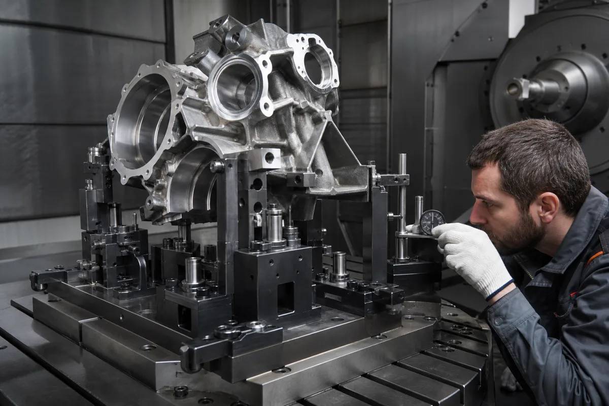
Workpiece fixture for machining cast housings: how the casting is located on supports and pins, and how the fixture base locates on the machine pallet
Dedicated milling fixtures for cast housings · locating a raw casting on supports, a cylindrical and a flattened pin in machined holes, and the zero-point interface to the machine pallet
A workpiece fixture, as covered here, is the dedicated steel fixture built for one cast part, such as a gearbox or pump housing, and bolted or clamped to the pallet of a machining centre. Its accuracy comes from two chains: how the casting sits on the fixture's supports and pins, and how the fixture body sits on the machine. Clamps only hold the part against those locators, so the buying questions are which features of the casting are used as datums, what pins and supports carry it, and what interface takes the fixture to the pallet.
Dedicated (part-specific) workholding fixtures for milling and boring cast or forged housings on machining centres: the fixture base or riser, rest pads and adjustable supports, locating pins and plugs, foolproofing pins, and the interface that locates the fixture on the machine table or pallet, including zero-point modules and their clamping pins. Hydraulic swing clamps, work supports and their sequencing are covered on the Hydraulic clamping system for machining fixtures page; machine vises on the Clamping jaws / vise page. Welding fixtures are covered on the Welding fixture jig page, sheet-metal body-in-white locating on the Assembly Fixture page, toggle-clamp weld fixtures on the Toggle-clamp clamping fixture page, and woodworking benches on the Work table page. Test fixtures for circuit boards are outside this page.
CNFX editorial research · Sources checked October 12, 2026 · 3 sources
First operation on a raw casting: three supports, two side locators, one end stop
Carr Lane's fixture design guide counts twelve degrees of freedom for a workpiece: movement both ways along x, y and z, and rotation both ways about each axis. Three supports under the primary surface restrict five of them, two locators on a side surface add three more, and one end locator adds a ninth; the remaining three are left to the clamps. [1]
For a casting that has not yet been machined, the same guide separates solid supports (fixed height, such as rest buttons) from adjustable supports, which it describes as used where the part varies in height and for cast or forged workpieces with uneven or irregular mounting surfaces. Equalizing supports float, so that as one side is pressed down the other rises by the same amount and both stay in contact. [1]
Carr Lane also warns against redundant location, meaning two locators controlling the same movement: because parts vary slightly in size, they are unlikely to touch both at once, and the extra locator can push the part off its true position or damage it. It advises taking the locating features from the way the drawing is dimensioned. [1]
Editorial note: on a housing like the one pictured, the first operation is where the raw cast faces carry the part; the faces and bores it machines then become the datums for later operations. Ask the fixture maker to show which cast surfaces carry the three, two and one locators, and whether any of them are adjustable.
Send the casting drawing with its datum scheme, the raw-casting model with draft and parting lines, and the operation sequence, so the fixture maker can place supports on surfaces that exist at that stage.
02
A cylindrical pin and a flattened pin in two machined holes for the second operation
Once the first operation has bored two holes in the housing, the part can be located on one round pin and one relieved pin. Carr Lane's example shows a plate and two pins restricting eleven of the twelve degrees of freedom, with the last left to a clamp. [1]
Halder's DIN 6321 data sheet describes the cylindrical pin (form B) as locating a workpiece in a toleranced hole, and the flattened pin (form C) as used to overcome differences in tolerances between holes or to position in one direction only; both are hardened and ground tool steel. The table lists the shank and fixture-hole sizes for the form C pins. [2]
Pin size starts from the hole at its maximum material condition, the smallest size the hole can have. Carr Lane's example is a hole allowed between .500 and .510 in, with a pin of .4995 in. [1] Editorial calculation: that leaves 0.0005 in (about 0.013 mm) clearance at the smallest hole and 0.0105 in (about 0.27 mm) at the largest, so a part with holes at the top of their tolerance can shift by that much on the round pin.
Give the hole sizes with their tolerances and the distance between them; ask which hole gets the cylindrical pin and which the flattened one, and how the flat is oriented to the line joining the holes.
03
Locating the fixture base on the pallet with zero-point modules
SCHUNK describes its VERO-S zero-point system as combining two functions, positioning and clamping, so that fixtures can be set up outside the machine and moved between machines with the same accuracy. [3]
The same overview gives holding forces for the NSE plus modules by clamping-pin screw size: 35 kN with M10, 50 kN with M12 and 75 kN with M16. Clamping pins come as type A (fixed), type B (positioned) and type C (with centering play), and SCHUNK states a repeat accuracy below 0.002 mm for its SPG 40 clamping pin with a flex cone. [3]
Editorial note: the three pin types do the same job at the pallet that the round and flattened pins do at the casting; one pin fixes the position, a second fixes rotation only, and the rest only pull down. Ask the fixture maker which pin type sits under each corner of the base, so that the base is not located twice in the same direction.
State the pallet or table interface on your machines (module make and size, pin pitch, or T-slot and key layout) so the fixture base is drilled for it.
04
Fixture tolerances as a share of the housing's tolerances, and locator spacing
Carr Lane's guide gives two tolerances for each locator, one on its size and one on its position, and sets them as a percentage of the workpiece tolerance, in a range it gives as 20% to 50%. It notes that halving a tolerance could multiply its cost by five. [1] Editorial calculation: for a bore position held to ±0.05 mm on the housing, that range puts the locator position at ±0.01 to ±0.025 mm.
On spacing, the guide shows that an error of .001 in in a locator's centre barely moves the part when locators are far apart but moves it noticeably when they are close, and it recommends spacing them as far apart as the part allows. It also asks for relieved locators and coolant drain holes or slots so chips and coolant do not lift the part off its supports. [1]
05
What to send for a dedicated housing fixture
Paste it into your enquiry below or into an email to a maker, then replace every bracket.
Part: [casting drawing and model; material; weight; datum scheme]
Operations: [operation sequence; faces and bores per operation; machine type]
Locating: [surfaces for supports; holes for round and flattened pins; adjustable supports]
Clamping: [manual or hydraulic; clamp points]
Interface: [pallet or table; zero-point module and pin layout]
Tolerances: [part tolerances; required fixture tolerances]
Checks: [inspection report of locator positions]
Explore company information and manufacturing capabilities, then discuss the scope of your project with a relevant supplier.
Share this page
Compiled and source-reviewed by the CNFX editorial team.
Each manufacturer above links to the page on that company's own website where the product is listed, with the date we checked it. How we source and review
· Page last updated 13 October 2026
Buyer questions
Why does a fixture use exactly six locators on a block-shaped part?
Carr Lane's 3-2-1 example: three supports restrict five degrees of freedom, two side locators three more and one end stop a ninth; the other three are left to the clamps. [1]
Why is one of the two locating pins flattened?
Halder describes the flattened DIN 6321 form C pin as overcoming tolerance differences between holes or positioning in one direction only, while the form B pin locates in a toleranced hole. [2]
How strongly does a zero-point module hold a fixture?
SCHUNK lists 7.5 kN pull-down for the VERO-S NSE plus 138, 25 kN with turbo, and holding forces of 35 to 75 kN depending on the M10 to M16 clamping-pin screw. [3]
Sources and what still needs a direct check
Sources checked 2026-10-12. Carr Lane's published fixture design principles (a US workholding component maker), Erwin Halder KG's DIN 6321 locating pin data sheet, and SCHUNK's VERO-S overview presentation.