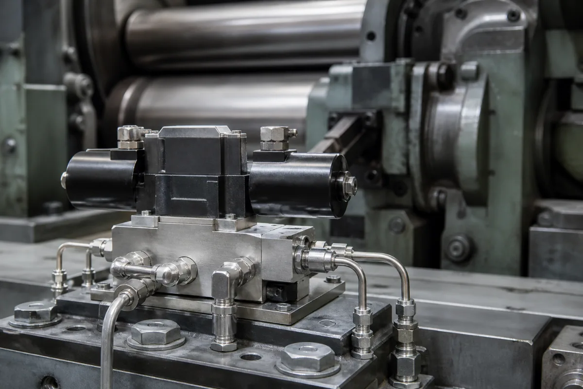
Electrohydraulic flow-control servo valves · Two-stage nozzle-flapper valves with mechanical spool feedback that meter hydraulic flow in proportion to a milliamp signal, specified by rated flow, pressure, step response, rated current, mounting pattern and body material
A hydraulic servo valve turns a small electrical signal into a precisely metered flow of hydraulic oil to a cylinder or motor, so position, force or speed can be controlled in a closed loop. Ask three things first: what flow and pressure the actuator needs, what dynamic response the control loop requires, and which signal, mounting pattern, body material and area rating the installation needs.
Electrohydraulic flow-control servo valves (two-stage, nozzle-flapper or similar pilot, mechanical or electrical feedback) for industrial closed-loop control. Proportional valves without servo performance, on-off solenoid valves (see solenoid valve), hydraulic gap control systems as a whole (see heavy-duty rolling mill hydraulic gap control system) and servo motors are outside this page.
CNFX editorial research · Sources checked October 11, 2026 · 4 sources
Moog describes its 761 Series as two-stage flow-control servo valves for 3-way and preferably 4-way applications, with a symmetrical nozzle-flapper torque motor pilot stage and mechanical feedback. Rated flows run from 0.5 to 75 l/min (0.125 to 20 gpm) at 35 bar (500 psi) pressure drop per spool land, that is 70 bar (1,000 psi) across the valve, in standard configurations of 4, 10, 19, 38 and 63 l/min. [1]
Maximum operating pressure is 315 bar (4,500 psi) with an aluminium body and 350 bar (5,000 psi) with a steel body. The 100% step response is under 4 to under 16 ms, measured at 3,000 psi system pressure, and Moog lists a very high response option. [1]
Editorial calculation: 315 bar is 31.5 MPa and 350 bar is 35 MPa; 3,000 psi is about 207 bar. [1]
Give the supplier the actuator and load, required flow at the available pressure drop, system pressure, required bandwidth or step response, control signal and coil configuration, mounting pattern, body material, fluid type and cleanliness, temperature range, hazardous-area classification, and the controller it will work with.
02
Compare the pilot stage for contamination tolerance
Moog's 761 Series uses a symmetrical nozzle-flapper pilot. [1] A jet pipe pilot is the main alternative. Kang et al. (Yanshan University, Sensors 2023) describe its pre-stage as converting oil pressure to kinetic energy in a single nozzle and back to pressure in two receiving holes. They state that its minimum channel size is large, on the order of 100 µm, giving good resistance to contamination; that if the single nozzle is totally blocked the main spool returns to centre because the two receiving holes see equal pressure; and that partial blockage only reduces performance without causing failure or runaway. They report jet pipe valves applied in jet engine hydraulic control and flight control systems. [4]
Their pressure-flow model for the pilot stage matched simulation within 2.3% for pressure and 0.0022 L/min for flow, and matched published test data within 2.19% for pressure characteristics. [4] Editorial note: whichever pilot is offered, state your fluid cleanliness and filtration in the enquiry and ask the supplier what null shift or failure position to expect if the pilot stage becomes contaminated.
Moog lists the 761 Series with a rated signal of 8 to 200 mA (single coil), ISO 10372-04-04-0-92 size 04 mounting, and weights of 1.0 to 1.7 kg. Options include high null bias, magnetic null adjust, vented motor cap, parallel internal wiring and reverse polarity, and intrinsically safe 761K versions are offered for hazardous areas. [1]
The mounting pattern in that designation comes from ISO 10372, Hydraulic fluid power — Four- and five-port servovalves — Mounting surfaces (published in Sweden as SS-ISO 10372, edition 1, approved 26 July 2002, 10 pages, ICS 23.100.50). Its scope fixes the dimensions of the surfaces servovalves mount on so that valves are interchangeable. It applies primarily to electrohydraulic flow-control servovalves, covers four-port valves and five-port valves whose pilot stage is supplied with fluid separately from the other stages, and may also be used for pressure-control servovalves; in a three-port application either service port, A or B, may be omitted. Because servovalves and certain proportional valves overlap in performance and application, the standard does not exclude a mounting surface to ISO 4401 instead. [3]
Editorial note: state in the order whether the manifold is drilled to the ISO 10372 surface or to an ISO 4401 surface, and whether the pilot is supplied internally (four-port) or from a separate port (five-port), so that a replacement valve from another maker fits the same manifold. [3][1]
Moog's white paper names the torque motor, flapper, spool and feedback mechanism as the basic elements: a small continuous flow passes through two opposed nozzles, the torque motor moves the flapper between them, and the resulting pressure difference shifts the spool, whose position is fed back mechanically. It says feedback mechanisms can reach life expectancies well above 1 billion cycles with the right materials and design, and that its carbide ball-in-hole feedback, used since 1994, wears comparably to sapphire with better field reliability. [2]
04
Find servo valve manufacturers
The manufacturer card below states what the reviewed source shows.
Ask any supplier for rated flow and flow curves, maximum and minimum pressure, step and frequency response, hysteresis and threshold, null shift with temperature and pressure, rated current and coil resistance, mounting pattern, seal materials, filtration requirement, certifications and repair service.
05
Trace what each part does
This is a functional reference built from the sources cited; it is not one maker's specification.
Fill the specification fields with values for your order
A servo valve quotation needs values for your actuator. The table explains each field, gives published values where a reviewed source states them, and says what to obtain from the supplier.
The manufacturer below lists electrohydraulic servo valves on its own website; each card links to the page reviewed. Confirm ratings, materials and approvals for your order.
AVIC Nanjing Servo Control System Co., Ltd.
Manufacturing site to be confirmed for the order
Lists electrohydraulic servo valves, with selection, application and maintenance guides.
Explore company information and manufacturing capabilities, then discuss the scope of your project with a relevant supplier.
Share this page
Compiled and source-reviewed by the CNFX editorial team.
Published product pages show what a company offers, not tested performance. Confirm the legal seller, factory and scope for your order. How we source and review
· Page last updated 13 October 2026
Buyer questions
How does a two-stage servo valve work?
A torque motor moves a flapper between two nozzles; the pressure difference shifts the spool, whose position is fed back. [2]
How fast do industrial servo valves respond?
Moog lists 100% step response of under 4 to under 16 ms for its 761 Series at 3,000 psi. [1]
What pressure can a servo valve body take?
Moog lists 315 bar for aluminium and 350 bar for steel 761 bodies. [1]
Which standard defines servo valve mounting surfaces?
ISO 10372 sets the mounting surface dimensions for four- and five-port servovalves so valves are interchangeable; ISO 4401 surfaces are not excluded. [3]
Why choose a jet pipe servo valve pilot?
Kang et al. state its smallest channel is on the order of 100 µm, giving good contamination resistance, and that a fully blocked nozzle lets the spool return to centre. [4]
Sources and what still needs a direct check
Sources checked 2026-10-11. Moog makes electrohydraulic servo valves. ISO 10372 (scope page published by the Swedish Institute for Standards) defines the mounting surfaces those valves bolt onto. A Yanshan University paper describes the jet pipe pilot stage.