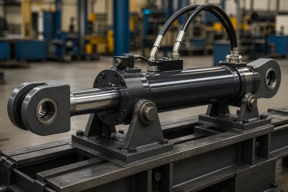
Hydraulic cylinder assembly for excavator booms (boom cylinder with pipe-rupture valve)
Excavator boom and arm cylinder assemblies with cylinder-mounted pipe-rupture valves · ISO 8643 and EN 474 lifting duty, flange sizes, flow and relief settings, response flow of flow-triggered fuses
On an excavator the boom cylinder is rarely delivered as a bare cylinder: the assembly includes the rod and base eyes with their bearings, the hose or tube connections and, on machines that lift loads on a hook, a pipe-rupture (hose-burst) valve bolted directly to the cylinder port. That valve decides whether a burst hose drops the boom or holds it. Settle three things with the cylinder supplier: whether the machine's lifting duty requires an ISO 8643 lowering control device, which valve type and flange size go on the boom and arm cylinders, and how the valve's flow and pressure settings match the cylinder's return flow and load pressure.
Boom, arm (stick) and adjusting cylinder assemblies for hydraulic excavators and similar mobile machines, including cylinder-mounted pipe-rupture and line-rupture valves and their settings. Single-rod industrial cylinders, with push and pull force, test pressure, mountings and cushioning, are covered on the Hydraulic cylinder page. Cylinder seal kits, tubes and rods sold as separate parts are outside this page.
CNFX editorial research · Sources checked October 12, 2026 · 3 sources
Pipe-rupture valve on the boom cylinder for excavators that lift on a hook
Bucher Hydraulics states that its excavator pipe-rupture valve is used wherever ISO 8643 and EN 474 require it, on excavators with a lifting device such as a load hook on the bucket, and names the lift (boom), stick and adjusting cylinders as the actuators it suits. It also recommends the valve on materials-handling and demolition machines where a burst line on an actuator could be dangerous. [1]
Hitachi Construction Machinery's patent on a pipe breakage control valve describes the hose rupture control valve unit as mounted on the bottom side of a boom cylinder or the rod side of an arm cylinder, connected between the cylinder port and the control valve. Its poppet main valve holds the load pressure on the bottom side with reduced leakage while the control valve is in neutral, lets the boom be lowered slowly under flow control, and includes a small relief valve that drains oil if an external force drives the bottom-side pressure too high. [3]
Bucher's CFS-E series does the same jobs: it prevents uncontrolled lowering after a pipe or hose rupture, holds the actuator when the main valve is centred, and carries a secondary pressure relief to protect the cylinder against overload. The valve is a flat design with a nose, so no sandwich plate is needed, and it uses standard SAE flange ports so it can be retrofitted to existing equipment. [1]
Give the cylinder supplier the machine and its lifting duty, which cylinders need a lowering control device, the valve make and type if the machine builder specifies one, port flange size, maximum load pressure, return flow when lowering, and whether emergency lowering is needed.
02
Size 16 or size 20: flow, pressure and flange data of a flange-mounted valve
The ratings below are Bucher's for its electrically proportional CFS-E valve; they show which values the cylinder port and the hydraulic circuit have to match. [1]
Bucher specifies a 12 or 24 V DC solenoid (±10%, 27 W nominal), a fluid temperature range of −20 to +80 °C, minimum cleanliness of ISO 4406 class 20/18/15 and a zinc-nickel coated body to DIN EN ISO 19598. In its standard function the valve only monitors the line and the main spool controls lowering; a load-bearing function, where the valve itself controls lowering, is offered on request. [1] Editorial calculation: 350 ÷ 250 = 1.4, so the size 20 valve carries 40% more flow than size 16 at the same 420 bar rating. [1]
Flow-triggered line rupture valves: choosing the response flow against the lowering flow
HAWE's type LB line rupture protection valves, rated to 500 bar and up to 250 l/min, are mounted directly on the cylinder and close when the flow out of it exceeds a preset trigger flow: flow forces press a spring-held plate onto the housing seat. A variant with an orifice in the plate lets a small flow pass in the locking direction. [2]
HAWE's worked example sets a gap of 1.3 mm for a response flow of 55 l/min and adds 2 l/min through the orifice, for an actual response flow of 57 l/min. As a reference value it gives a ratio of response flow to normal return flow of approximately 1.5 for manually operated directional valves and about 2 for solenoid-operated or other fast-switching valves. [2]
HAWE warns that on large-volume cylinders or at high load pressures the decompression surge when the directional valve switches can close the valve during normal work, and that an orifice on the outlet side, outside the monitored line, may be needed; with very different loads, the orifice can reduce the lowering speed at low load. [2] Editorial calculation: a cylinder returning 100 l/min when lowered through a solenoid valve would, on HAWE's reference ratio of about 2, need a response flow near 200 l/min, inside the 250 l/min rating. [2]
04
Pilot-operated seat valve or flow fuse on the cylinder
1 company lists this product among what they make. Company figures are quoted from each
company's own website; every card states where the relationship came from.
Yoonad Group Co., Ltd.
Manufacturing site to be confirmed for the order
Lists replacement boom hydraulic cylinder assemblies for standard and mini excavators, with alloy-steel tubes and induction-hardened, hard-chrome-plated rods; bore, stroke, mounting dimensions and seals can be customised.
Explore company information and manufacturing capabilities, then discuss the scope of your project with a relevant supplier.
Share this page
Compiled and source-reviewed by the CNFX editorial team.
Each manufacturer above links to the page on that company's own website where the product is listed, with the date we checked it. How we source and review
· Page last updated 13 October 2026
Buyer questions
When does an excavator boom cylinder need a pipe-rupture valve?
Bucher says its valve is used wherever ISO 8643 and EN 474 require it for excavators with a lifting device such as a load hook, on the boom, stick and adjusting cylinders. [1]
Where is a hose rupture valve mounted on an excavator?
Hitachi's patent describes it on the bottom side of the boom cylinder or the rod side of the arm cylinder, between the cylinder port and the control valve. [3]
How is the response flow of a line rupture valve chosen?
HAWE gives a reference ratio of response flow to normal return flow of approximately 1.5 for manual directional valves and about 2 for fast-switching solenoid valves. [2]
Sources and what still needs a direct check
Sources checked 2026-10-12. Bucher Hydraulics and HAWE are valve makers publishing data sheets for their own pipe- and line-rupture valves; Hitachi Construction Machinery's European patent application describes how such a valve is placed on boom and arm cylinders. ISO 8643 and EN 474 themselves set the requirements.