Driving a folding mechanism from a cam table instead of a cam disc
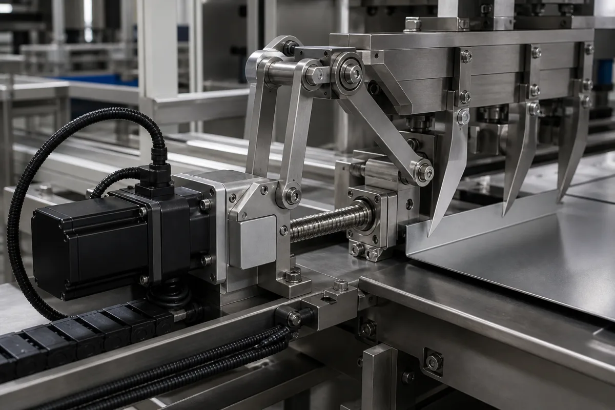
The illustrated unit folds sheet material with a row of pointed blades swung by a linkage; the linkage is pushed by a ball screw, and the ball screw is turned by a servo motor with its cables in a drag chain. Nothing in it is a cam, yet the blades have to move like a cam follower: wait, swing, hold, return, at the same point of every machine cycle and at whatever speed the line runs. That is electronic camming, and Tolomatic, Motion Control Tips and Danfoss explain what it consists of.
Covers actuation systems that drive folding mechanisms in production machines with servo motors on electronic cams: mechanical cam systems and their profiles, the three parts of an electronic cam, cam tables and master axes, drive functions such as virtual master, marker correction and cam boxes, and the ball-screw and linkage mechanics behind the servo. Pneumatic actuators are on the pneumatic actuator page; pneumatic supply systems on 3198; DC screw adjustment actuators on 1344; roller-screw actuators on 3342; PLC cam tables over EtherCAT on Central PLC Controller (652).
CNFX editorial research · Sources checked October 13, 2026 · 3 sources
What the blades have to do: a cam profile against the machine's master position
Tolomatic describes the purpose of a mechanical cam system as converting continuous rotary motion into intermittent linear or rotary motion: a master input driven at constant speed, a cam, and a follower.
On a line shaft, every cam scales with the shaft speed: run the machine slower and every motion and dwell slows in proportion. Tolomatic calls this one of the strengths of camming, and it is the behaviour an electronic system has to reproduce for a folding station that sits among other stations.
Motion Control Tips describes the same idea from the other side: a cam is essentially a motion profile executed by mechanical means, and in electronic camming the profile is defined in a table as a set of x–y points.
Element
Tolomatic's description
Master
Provides continuous motion, driven by a constant-speed motor or line shaft
Follower
Creates the intermittent motion, here the blade swing
Cam profile
Graph of master axis position (horizontal) against follower position (vertical), including dwell times
Steep profile
Fast acceleration and long dwell
Shallow profile
Lower acceleration and longer dwell time
Constant-acceleration cam
S-curve position profile, linear velocity profile
Cycloidal cam
S-curve velocity profile
Tolomatic's 'steep' and 'shallow' descriptions are qualitative; the actual profile is set by the fold geometry and the dwell the material needs.
02
Three parts of an electronic cam: actuator, controller with variable gearing, master encoder
Tolomatic lists what is needed to reproduce a mechanical cam electronically.
Tolomatic's case-packer example shows the payoff: with every axis cammed to one master, all axes speed up and slow down in step with the master, instead of needing a separate velocity profile for each machine speed. Motion Control Tips names the main advantage as changing motion profiles quickly without mechanical adjustment.
Tolomatic's bagging example uses four ball-screw linear actuators to position bags of varying size, with right-hand and left-hand screws coupled so that one motor gives two axes; a format change becomes a table change rather than a cam change.
Part
Role
In the illustrated unit
Electric actuator
Provides the follower motion
Servo motor turning a ball screw, which pushes the blade linkage
Motion controller with variable gearing
Executes the cam relation between master and follower
Drive or controller holding the cam table
Master encoder or equivalent
Detects speed and position of the master axis
Line-shaft or machine master position
The column for the illustrated unit is an editorial mapping of the three parts onto the pictured mechanism.
03
Drive functions that replace the cam box: virtual master, marker correction, cam editor
Danfoss's VLT Motion Control Option MCO 305 is an example of a drive-level electronic cam, listed with the functions that replace mechanical cam discs and cam boxes.
Danfoss lists the benefits as fewer mechanical parts and lower maintenance, smaller machines, and curves that can be designed and modified in the cam editor, including during commissioning.
Resolution follows from the table size: a 3,600-point cam over one 360° master cycle places a point every 0.1° of master position (Editorial calculation), which the drive interpolates between.
Function (Danfoss MCO 305)
Use in a folding station
Speed and position synchronizing, with marker corrections
Lock blade motion to the line and correct it to print or product marks
Virtual master
Run the cam against a software master when no physical line shaft exists
Cam control with online marker correction
Replace mechanical cam discs; adjust phase while running
Cam box
Switch outputs at set master positions, as a mechanical cam box did
Graphical cam editor; profiles modifiable during commissioning
Shape the fold motion without new hardware
Interpolation between cam points; limited jerk function
Function names are Danfoss's for the MCO 305; other drives offer equivalent features under their own names.
04
What to specify for a servo folding actuation system
Paste it into your enquiry below or into an email to a maker, then replace every bracket.
Give the fold geometry and blade swing, the required motion and dwell within the machine cycle, the machine speed range, the master source (line-shaft encoder or virtual master), any print or product mark the motion must follow, the moving mass and linkage geometry, and format changes expected. Ask for the servo, ball screw and linkage sizing, the cam table resolution and interpolation, jerk limiting, marker-correction capability, encoder types, and how a new format's cam profile is created and stored.
Explore company information and manufacturing capabilities, then discuss the scope of your project with a relevant supplier.
Share this page
Compiled and source-reviewed by the CNFX editorial team.
Each manufacturer above links to the page on that company's own website where the product is listed, with the date we checked it. How we source and review
· Page last updated 13 October 2026
Buyer questions
What does an electronic cam need?
Tolomatic lists an electric actuator for the follower motion, a motion controller with variable gearing, and a master encoder or another way to read the master axis speed and position. [1]
How is an electronic cam profile stored?
Motion Control Tips describes cam profiles defined in a table as a set of x–y points, executed by servo motors, drives and controllers with electronic gearing. [2]
What is a virtual master?
Danfoss's MCO 305 lists a virtual master among its synchronizing functions, so axes can be cammed to a software master rather than a physical shaft. [3]
Why replace a mechanical cam on a folding station?
Motion Control Tips names the ability to change motion profiles without mechanical adjustment; Danfoss adds fewer mechanical parts and lower maintenance. [2][3]
Sources and what still needs a direct check
Sources checked 2026-10-13. An actuator maker's explanation of electronic camming, a trade-site FAQ on the same subject, and a drive maker's motion control option brochure.