Editorial Technical Reference

Alignment System

This page explains how Alignment System is classified within Machinery and Equipment Manufacturing. Technical values and manufacturer relationships are research references; confirm the current specification and supplier evidence for each order.

Technical Definition & Core Assembly

A precision positioning subsystem within a Body Drop Station that ensures accurate alignment of components during assembly or processing operations.
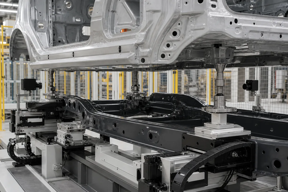
Representative product image. Confirm appearance and specifications with the manufacturer.

Product Specifications

Technical details and manufacturing context for Alignment System

Definition
The Alignment System is a critical component of the Body Drop Station responsible for precisely positioning and orienting workpieces or assemblies. It ensures components are correctly aligned before, during, or after the drop/placement operation, maintaining manufacturing tolerances and preventing misalignment-related defects in automated production lines. The system typically uses a combination of sensors (optical, laser, or mechanical), actuators (pneumatic, hydraulic, or servo-electric), and control logic to detect position deviations and make micro-adjustments. It compares the actual position of the component against programmed reference points and corrects any misalignment through controlled movement of positioning elements. The system is designed for integration into automated assembly lines, particularly in the automotive and heavy machinery sectors, where precise alignment is essential for quality and efficiency. Materials commonly used in its construction include aluminum alloy, stainless steel, and engineering plastics, chosen for their strength, durability, and resistance to wear. The system's positioning accuracy tolerance is specified in millimeters (mm), and the exact value must be confirmed for the specific model and application. The Alignment System operates within a defined scope, focusing on the alignment of components during the drop/placement process. Its working principle relies on real-time feedback from sensors to adjust the position of the workpiece, ensuring it meets the required tolerances. Selection of the appropriate system depends on factors such as the size and weight of the components, the required accuracy, and the environmental conditions of the production line. Interfaces typically include power supply, control signals, and communication with the central control system. Verification of the system's performance involves checking alignment accuracy against the specified tolerance and ensuring consistent operation over time. Maintenance signals may include increased deviation from the reference position, unusual noise from actuators, or sensor malfunctions. Failure boundaries are defined by the system's inability to maintain the required tolerance, which could lead to production defects. It is essential to verify model-specific values and standards with the legal manufacturer or supplier before procurement.
Working Principle
The system uses sensors to detect the actual position of the component relative to a reference point. Control logic compares this with the programmed target position. If a deviation is found, actuators make micro-adjustments to correct the alignment. This process is continuous, ensuring the component remains correctly positioned throughout the operation.
Common Materials
Aluminum alloy, Stainless steel, Engineering plastics
Technical Parameters

What to specify in your RFQ

  • Positioning accuracy tolerance in mm

These are the quantities to specify to the manufacturer when sizing or requesting a quote. The manufacturer's own documentation governs the exact figures and applicable standard.

Components / BOM
  • Positioning Sensors
    Detect actual position of components and provide feedback to control system
    Material: Stainless steel housing with optical/electronic components
  • Alignment Actuators
    Provide controlled movement to correct position deviations
    Material: Aluminum alloy with steel guide rails
  • Control Module
    Process sensor data and command actuator movements
    Material: Electronic components in protective casing

Applied To / Applications

This component is essential for the following industrial systems and equipment:

Industrial Ecosystem & Supply Chain Structure

Complementary Systems
Downstream Applications
Specialized Tooling

Application Fit & Sizing Matrix

Operational Limits
pressure: Atmospheric to 1.5 bar (max external pressure)
other spec: Positioning accuracy: ±0.01 mm, Repeatability: ±0.005 mm, Vibration tolerance: <0.5 g RMS
temperature: 0°C to 50°C (operating), -10°C to 60°C (storage)
Media Compatibility
✓ Clean dry air ✓ Non-corrosive gases (N2, Ar) ✓ Light machine oils (ISO VG 32-68)
Unsuitable: Abrasive slurry environments with particulate >50 μm
Sizing Data Required
  • Component weight and center of gravity
  • Required positioning accuracy and repeatability
  • Available installation envelope (XYZ dimensions)

Reliability & Engineering Risk Analysis

Failure Mode & Root Cause
Misalignment-induced bearing failure
Cause: Incorrect shaft alignment during installation or thermal growth, leading to excessive radial/axial loads on bearings, causing premature wear, overheating, and eventual seizure or catastrophic failure.
Coupling component fatigue and fracture
Cause: Cyclic stresses from persistent misalignment (angular or parallel) exceeding material endurance limits, resulting in cracking, bolt shearing, or elastomeric element degradation in flexible couplings, often exacerbated by improper torque or lubrication.
Maintenance Indicators
  • Abnormal vibration or audible knocking during operation, indicating dynamic imbalance or mechanical interference from misalignment.
  • Rapid temperature rise in bearings or coupling housings, detected via thermal imaging or touch, signaling excessive friction due to misaligned loads.
Engineering Tips
  • Implement laser alignment during installation and after major maintenance, ensuring tolerances within manufacturer specs (e.g., ≤0.05 mm offset, ≤0.1 mm/m angular), and re-check post-thermal stabilization to account for operational expansion.
  • Establish a predictive maintenance routine with vibration analysis and thermography at regular intervals (e.g., quarterly), using trend data to detect early misalignment and schedule corrections before failure occurs.

Indicative industry ranges for design and RFQ preparation. Confirm the exact figures and applicable standard with the manufacturer before specifying.

Compliance & Manufacturing Standards

Applicable Standards
ISO 1101:2017 - Geometrical product specifications (GPS) - Geometrical tolerancing ANSI/ASME Y14.5-2018 - Dimensioning and Tolerancing

Quoted from the published standard.

Manufacturing Precision
  • Parallelism: +/-0.01mm per 100mm length
  • Concentricity: 0.005mm TIR (Total Indicator Reading)
Quality Inspection
  • Laser Alignment Test (ISO 230-1:2012)
  • Coordinate Measuring Machine (CMM) Verification

Manufacturers of Alignment System

Manufacturer profiles associated with Alignment System.

Sourcing Alignment System from China?
Tell us your specification and target quantity — we will match it against manufacturer records and come back with the factories that fit.
Request manufacturers We manufacture this

Manufacturer listings support early research and capability understanding. They are not certification, ranking, or transaction guarantees.

Technical documentation
Request current drawings, revision history, and a signed specification sheet.
Manufacturing capability
Verify equipment lists, process limits, capacity, and representative production evidence.
Inspection readiness
Confirm test methods, calibrated equipment, sampling plans, and traceable reports.
Supplier transparency
Check the legal entity, factory address, ownership, certifications, and direct contacts.

CNFX does not score or rank suppliers. Buyers must verify all claims and documents with the legal manufacturer before ordering.

Supply Chain Compatible Machinery & Devices

Automated Powder Coating System

Integrated industrial system for applying dry powder coatings to metal substrates.

Explore Specs →
Centrifugal Pump Impeller

The centrifugal pump impeller is a critical rotating component that converts mechanical energy from the motor into kinetic energy in fluid systems.

Explore Specs →
High-Precision CNC Laser Cutting Machine

Computer-controlled industrial machine using focused laser beams to cut sheet metal with micron-level accuracy.

Explore Specs →
Industrial-Grade Hydraulic Cylinder Piston Rod

This industrial-grade piston rod is a precision-ground cylindrical component designed for use in hydraulic cylinders.

Explore Specs →

Frequently Asked Questions

What is the primary function of the Alignment System?

The primary function is to precisely position and orient workpieces or assemblies during the drop/placement operation in a Body Drop Station, ensuring they are correctly aligned to maintain manufacturing tolerances and prevent defects.

What materials are commonly used in the Alignment System?

Common materials include aluminum alloy, stainless steel, and engineering plastics. These are selected for their strength, durability, and resistance to wear, but specific grades must be confirmed with the manufacturer.

How does the Alignment System ensure accuracy?

It uses sensors to detect position deviations, control logic to compare actual position against reference points, and actuators to make micro-adjustments, ensuring the component is correctly aligned.

What should be verified before purchasing an Alignment System?

You should verify the positioning accuracy tolerance (in mm) for your specific model and application, as well as any applicable standards, with the legal manufacturer or supplier.

Data Basis

Editorial classification, named public sources where available, and source-reviewed manufacturer records.

Preliminary Technical Classification
This page supports structured research, RFQ preparation, and supplier evaluation. It does not replace buyer-led supplier qualification, standards review, or technical approval.
Buyer enquiry

Request manufacturing insight for Alignment System

Ask for use case, specification boundaries, supplier type, and RFQ preparation information for this product.

Where it goes
Straight to the CNFX editorial desk, and to the manufacturer if this product is linked to a claimed profile. Nothing is broadcast to a supplier list.
Your details stay here
We do not sell or rent enquiry data, and we do not add you to a mailing list. Used only to answer this request.
No commission, no middleman
CNFX is a directory. We take no cut of any order and never negotiate on a supplier's behalf.
What we don't claim
A listing is not an endorsement. Qualify every supplier and verify every figure yourself before ordering.

Your business information is used only to process this request.

Thank you! Your message has been sent. We'll respond within 1–3 business days.
Sorry, we couldn't send your message. Please try again, or email us at contact@cnfx.com.

Need to Manufacture Alignment System?

Compare manufacturer profiles with relevant product and process capability.

Previous Product
Airflow Control Dampers
Next Product
All-Terrain Crane
Get QuotesChat