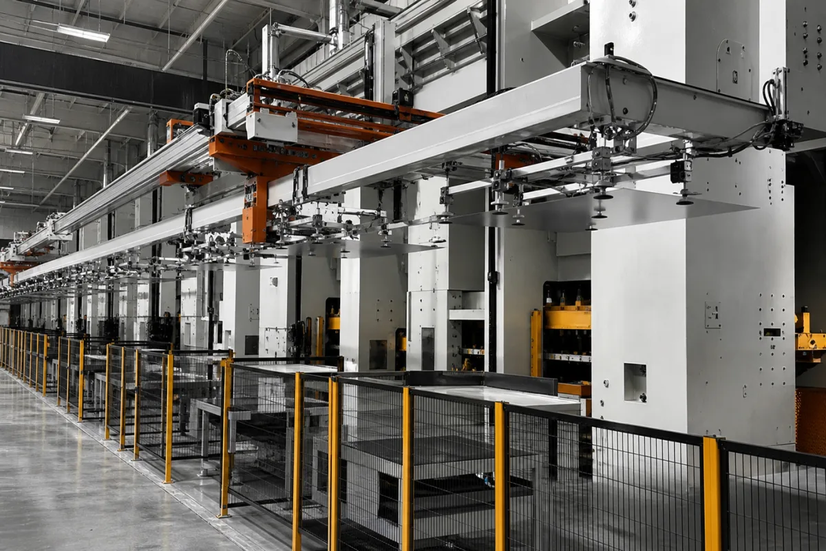
Crossbar transfer system for tandem press lines: servo feeders that carry body panels on suction-cup tooling from one press to the next
Sheet-metal press shops · the servo crossbar that lifts a formed panel out of one die on suction cups, carries it across the press gap and lays it in the next die
In a tandem press line each press holds one die, and the panel has to travel from die to die between strokes. A crossbar feeder does this with a beam across the press width carrying suction cups: it reaches into the open die, picks the panel up, carries it across the gap and sets it into the next die while the slide is up. Its speed, the mass of the bar and tooling it accelerates, and the press pitch it has to cover decide how many parts a minute the whole line makes.
Servo crossbar transfer feeders mounted between the presses of a tandem press line for sheet-metal body panels: the linear-servo carriages, the crossbar and its suction-cup tooling, extra axes that turn or separate double parts, and the automatic change of crossbar tooling with the dies. Destacking and end-of-line stacking are mentioned only where they set the line output. Presses and press lines as a whole are covered on the Automotive body panel stamping press page and the Automated stamping lines page; six-axis and 3- to 5-axis robots that load and unload presses on the Industrial robot arm for press tending and stamped-part transfer page; hot forging transfer on the Automated hot forging line page; coil-fed progressive work with a servo strip feed on the High-speed stamping module for small parts page; and powder pressing with its own loading carriage on the Ceramic tile press page. The Automotive body panel stamping press page treats the presses, die cushion and line types; this page treats only the crossbar link between them. Belt, roller and chain conveyors between machines are covered on the Part transfer conveyor for metal fabrication cells, Conveyor section and Main line conveyor between machining cells pages, and pallet transfer modules on the Pallet conveyor system transfer modules page.
CNFX editorial research · Sources checked October 13, 2026 · 4 sources
Parts per minute against press stroke rate: what a crossbar-linked servo line actually delivers
Schuler's ServoLine data separate the stroke rate a press can run from the output the whole line, crossbar feeders included, delivers.
Editorial calculation: at 23 parts a minute the line releases a finished part every 2.6 s, and the crossbar in each press gap has to complete its pick, carry, place and return within that time. The brochure gives an output range of 16 to 23 strokes a minute across the ServoLine sizes and states that the slide movement of each press can be programmed for the forming process, the die and the parts transport. [1]
Schuler describes its Crossbar Feeder as offering seven degrees of freedom, with two additional servo axes that can swivel double parts away from each other, rotate them or shift them in the feed direction. [1] The same line produces single, double or quadruple parts, and at the end of the line up to four robots stack single parts and up to eight robots stack double and quadruple parts. [1] For a two-out die, the extra axes are what let the crossbar change the spacing or orientation of the two panels between operations.
Editorial calculation: line output as share of max. press stroke rate
82 %
82 %
80 %
Ask for the output in parts per minute at your heaviest panel and press pitch, not the maximum press stroke rate, and whether the figure holds for double parts with the extra crossbar axes in use.
02
What the crossbar carries: 120 kg of blank and tooling, carbon-fibre bars and 25 m/s² across a 6 m press pitch
Strothmann's High Speed Transfer for a tandem line at Shanghai Superior Die Technology is one of the few crossbar systems with its payload, pitch and acceleration published together.
The bar itself is part of the payload. Strothmann attaches the tooling to a crossbar made of carbon-fibre reinforced plastic (CFK) in both its CompactTransfer and High Speed Transfer, and gives the reasons as low weight, high strength and a low natural frequency, which make high acceleration easier to reach. [4] Editorial calculation: at 15 strokes a minute each transfer cycle across the 6 m pitch has 4 s, and every kilogram of bar and suction cups counts against the 120 kg rating that the blank shares. [2]
The travel curve was set with Siemens press simulation software, and the transfer is fastened to the press frame in the direction of travel with all modules above floor level, so no expansion tanks or supply cables go into the press basement. [2] The FEEDERplus6 is described as a transfer that unloads, orients and feeds parts by itself and is programmed like a standard robot, aimed at small press gaps. [3]
Give each supplier the heaviest and largest panel per operation, the press-centre distance, the die opening available to the crossbar, and whether double parts must be turned or separated between dies.
03
Changing crossbar tooling with the dies, and retrofitting a crossbar to an existing line
Every die set needs its own crossbar tooling, so the tooling change runs inside the die change.
Schuler lists a fully automated die and tooling change in three minutes, with only one tooling per press gap, and describes the ServoLine die change as taking less than 3 minutes, supported by preselection of the change type and a display of the duration of the last two die changes. [1] In Strothmann's High Speed Transfer the floor space left free by the above-floor modules is used by tooling carts that drive the crossbar tooling to the transfer point automatically while the dies are changed. [2]
For existing lines, Strothmann developed the CompactTransfer to retrofit high-capacity suction presses, with stroke figures of up to 16 strokes a minute, and reports the sixth system installed in Mexico in 2016; the High Speed Transfer is based on it and is used both in new tandem lines and in retrofits. [4][2] The FEEDERplus6 is also offered for retrofitting older presses. [3]
For a retrofit, state the press-centre distances, the existing press stroke rates and drives, whether the presses can be synchronised electronically, and where tooling carts can stand during die change.
04
Data for a crossbar transfer enquiry
Paste it into your enquiry below or into an email to a maker, then replace every bracket.
Line: [number of presses; press-centre distances; new line or retrofit]
Presses: [stroke rates; slide stroke; servo or mechanical drive; die opening at transfer]
Parts: [largest blank and panel per operation; mass; single, double or quadruple]
Output: [parts per minute required at the heaviest panel]
Tooling: [suction cups or grippers; crossbar material; tooling sets per die]
Die change: [target time; tooling cart space; automatic tooling coupling]
Motions: [turn, separate or shift double parts between dies]
Explore company information and manufacturing capabilities, then discuss the scope of your project with a relevant supplier.
Share this page
Compiled and source-reviewed by the CNFX editorial team.
Each manufacturer above links to the page on that company's own website where the product is listed, with the date we checked it. How we source and review
· Page last updated 13 October 2026
Buyer questions
Why is line output lower than the press stroke rate?
In Schuler's ServoLine data the line outputs 23, 18 and 16 parts a minute where the presses can stroke at up to 28, 22 and 20; editorial calculation, about 80 to 82 %. [1]
How much can a crossbar feeder carry?
Strothmann's High Speed Transfer is rated at 120 kg for blank and tooling, for blanks up to 4,100 × 2,100 mm; its FEEDERplus6 models carry 80 or 125 kg including tooling. [2][3]
Why use carbon-fibre crossbars?
Strothmann states that its CFK crossbar is lightweight, very strong and has a low natural frequency, making high acceleration easier to reach. [4]
How fast is a crossbar tooling change?
Schuler lists a fully automated die and tooling change in three minutes for its ServoLine, with one tooling per press gap. [1]
Sources and what still needs a direct check
Sources checked 2026-10-13. A Schuler brochure gives output, stroke rate and die data for servo press lines linked by Crossbar Feeders; Cutting Tool Engineering product notes and a Plant Automation Technology profile give Strothmann's crossbar transfer payloads, press spacing, acceleration and crossbar material.