Automatic tool changer (ATC) reliability and testing: where tool changers fail, what a test bench measures on the arm and magazine, and the GB/T 39829 and GB/T 39954 test methods
The magazine-and-arm automatic tool changer judged on how it fails and how it is tested · where failures occur, what a reliability test bench measures, and the 2021 Chinese test-method standards for ATCs
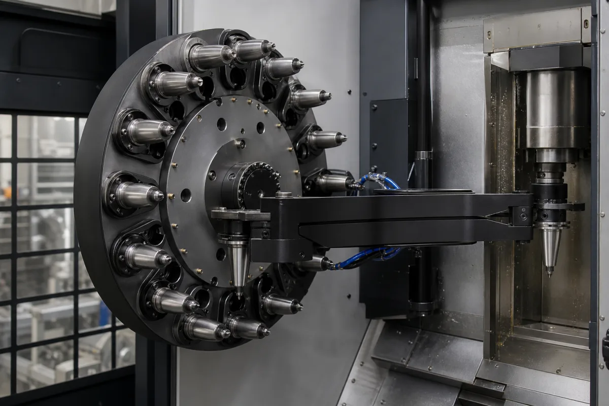
An automatic tool changer is the unit that takes a tool from the magazine, swaps it with the one in the spindle and returns the old tool, hundreds or thousands of times a shift. Machine builders quote its tool-change time and tool limits, but the figure that decides whether a machining centre keeps running unattended is how often the changer fails and how early a fault can be seen coming. Research groups and standard bodies have therefore treated the magazine and ATC as a unit to be reliability-tested: logging which part fails and why, measuring the arm's motion, the pocket's position, vibration and noise on a test bench, and fitting failure data to statistical models. The picture shows the kind of unit concerned: a disc magazine with taper tool holders in its pockets and a double-gripper arm reaching across to a spindle that holds a tool.
Automatic tool changers of machining centres as a unit (magazine, change arm and tool transfer), treated through their reliability: failure modes and their shares, condition and performance test parameters, reliability test benches and models, and the Chinese test-method standards for tool magazines with ATC. Sizing a tool magazine for tool count, tool size and mass is covered on the CNC tool magazine page; the double-gripper arm and its cam box on the Tool change arm page; magazine drums and tool pots on the Tool magazine drum page; cam indexers on the Indexing mechanism page. Robot tool changers and lathe turrets are outside this page.
CNFX editorial research · Sources checked October 13, 2026 · 5 sources
Arm 41.7 %, magazine 33.3 %, tool transfer 16.7 %: where the faults of a chain-magazine ATC were found
Researchers at Dalian University of Technology collected failure data from accelerated tests and customer feedback on a chain-type magazine and ATC built by Dalian Golden CNC for large horizontal machining centres, and grouped the major failures by location.
The same paper cites earlier data that more than 50 % of the faults of CNC machining centres are caused by the tool magazine and ATC. [1] It traces arm faults to the arm not reaching its designed position and to poor dynamic performance during the change, linked to an assembly method whose accuracy depends on the fitter and to cam wear, and recommends checking the arm's angular and linear displacement at intervals; tool drops it attributes to severe vibration that jams the tool-orienting part and stops the servo motor. [1] The studied LS series changes a tool in 5 to 10 seconds, takes single tools up to 30 kg, conveys at 20 to 30 m/min and holds up to 120 tools. [1]
Two other groups have published reliability models for magazines and ATCs. Researchers at KIMM in Korea built a reliability test bed for the ATC of a high-speed line centre and report failure rate, MTBF and reliability for its components. [3] A 2019 study of field failure data from a circular tool magazine and ATC fitted the time between failures to a Weibull distribution, noting that few studies of magazine and ATC failure existed. [2]
Location
Failures listed
Share of major failures
ATC (change arm / manipulator)
Wrong arm movement; failure inserting or drawing a tool; arm slipping the tool
Ask the supplier for field or test failure data by location (arm, magazine, transfer, drive), the number of tool changes in its endurance test, and the MTBF it can document.
02
Arm acceleration, pocket positioning error up to 1.0985 mm, and noise under 75 dB: what the test bench measured
The Dalian test system measures the parameters that drift before a failure, so that a repair can be scheduled when a threshold is crossed.
The authors explain that a pocket positioning error leaves the chain link out of line with the tool-orienting part at the change position, so that pushing the pot in or out can crash it, with consequences from vibration and noise to a broken compression bar, a damaged air system and a tool thrown out; the positive deviations they measured correspond to the upper chain in tension and the lower chain slack under gravity. [1]
Editorial calculation: the largest measured pocket deviation, 1.0985 mm, is about four times the 0.2776 mm average; the gap between the roughly 60 dB maximum measured and the 75 dB limit is 15 dB, a factor of about 5.6 in sound pressure (10^(15/20)). [1]
Test parameter
How it is measured
Result or limit reported
Arm angular and axial displacement and acceleration
PSD-based 3-D coordinate instrument tracking an LED on the arm, plus a wireless acceleration sensor
Largest tangential acceleration at the start of tool gripping and end of tool return; axial creep during drawing and inserting [1]
Magazine positioning error
Vertical deviation between ideal and actual pocket position at the change point, from industrial-camera images, eleven positions
Average 0.2776 mm; maximum positive 1.0985 mm; minimum negative 0.0095 mm [1]
Vibration of the tool-orienting part
Three-axis vibration sensor on the tool-orienting part
JB/T 10791.1-2007 limit below 75 dB; maximum measured about 60 dB, a few readings above 75 dB, door opening the main source [1]
Ask which parameters the supplier checks at acceptance and service (arm displacement, pocket positioning, vibration, noise) and the thresholds that trigger adjustment.
03
GB/T 39829-2021 and GB/T 39954-2021: reliability and performance test methods for tool magazines with ATC
China published two national test-method standards for the magazine-and-ATC unit on the same day.
Both list the National Machine Tool Quality Supervision and Testing Center, Jiangsu Desu Intelligent Machinery and Hohhot Zhonghuan among the main drafters, with Beijing Machine Tool Research Institute. [4][5] The noise limit used in the Dalian study came from the earlier machinery-industry standard JB/T 10791.1-2007. [1]
Standard
English title
Dates and responsibility
GB/T 39829-2021
Tool storage with automatic tool changer — Reliability test method
Issued 2021-03-09, in force 2021-10-01; recommended national standard under TC22/SC10 (functional components of metal-cutting machine tools) [4]
GB/T 39954-2021
Tool storage with automatic tool changer — Specification of performance test
Issued 2021-03-09, in force 2021-10-01; same committee [5]
State which test standard the acceptance and endurance tests should follow, and ask for the report rather than the claim.
04
Data for an automatic tool changer enquiry
Paste it into your enquiry below or into an email to a maker, then replace every bracket.
Machine: [vertical/horizontal machining centre; spindle taper]
Magazine: [disc, drum or chain; tool count]
Tools: [max diameter; length; single and total mass]
Change time: [tool-to-tool; chip-to-chip]
Reliability evidence: [failure data by location; MTBF; endurance test changes]
Test standard: [GB/T 39829-2021; GB/T 39954-2021; other]
Condition checks: [arm displacement; pocket positioning; vibration; noise]
Service: [adjustment intervals; spare parts]
Explore company information and manufacturing capabilities, then discuss the scope of your project with a relevant supplier.
Share this page
Compiled and source-reviewed by the CNFX editorial team.
Each manufacturer above links to the page on that company's own website where the product is listed, with the date we checked it. How we source and review
· Page last updated 13 October 2026
Buyer questions
Where in an automatic tool changer do failures occur?
In the Dalian University of Technology study of a chain-magazine ATC, 41.7 % of major failures were at the change arm, 33.3 % in the magazine, 16.7 % in the tool conveying mechanism and 8.3 % elsewhere. [1]
How large is a tool pocket positioning error?
Across eleven positions the study measured an average of 0.2776 mm and a maximum positive deviation of 1.0985 mm. [1]
Is there a standard for testing ATC reliability?
Yes. China's GB/T 39829-2021 sets a reliability test method and GB/T 39954-2021 a performance test method for tool storage with automatic tool changer, both in force since 1 October 2021. [4][5]
How noisy may a magazine and ATC be?
The Dalian study applies the JB/T 10791.1-2007 limit of below 75 dB; its measured maximum was about 60 dB with a few readings above 75 dB. [1]
Sources and what still needs a direct check
Sources checked 2026-10-13. Five documents from four publishers: a Dalian University of Technology paper in Sensors & Transducers (IFSA, 2014), a 2019 Inderscience abstract on time between failures of a circular magazine and ATC, a 2005 KSPE conference abstract from KIMM, and the national standard records for GB/T 39829-2021 and GB/T 39954-2021 on China's standards information platform (SAMR).