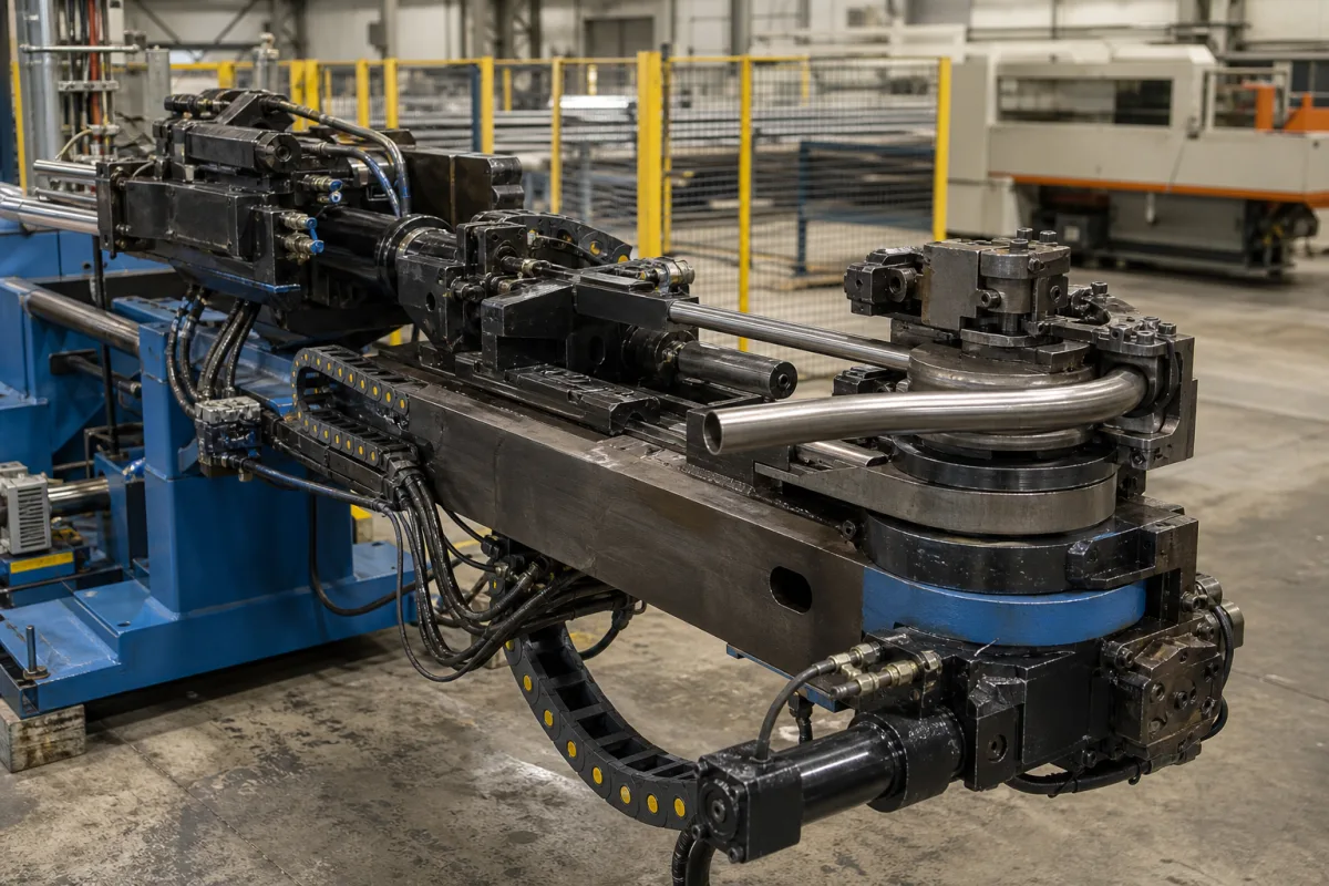
Bending arm assembly of a rotary-draw tube bender: the swing arm that turns the bend die and carries the clamp die, from Eaton Leonard's patented head to a 200°-per-second electric CNC arm
The swinging arm, bend die and clamp die at the head of a rotary-draw tube bender · clamp length and stroke, arm speed and bend angle, and how pressure die and wiper work against the arm
On a rotary-draw tube bender the tube is not pushed round a die; it is clamped to the bend die and dragged round it. The parts that do that dragging form the bending arm assembly: an arm, journalled on the same vertical axis as the bend die, that swings through the bend angle and carries the clamp die and its closing mechanism. The pressure die and wiper die stay on the fixed side of the head and resist or follow the tube. Specifying the arm means fixing the bend angle and direction it can sweep, how fast and how repeatably, the clamp die's length and stroke, the radius range of bend dies it can carry, and how it is coordinated with the pressure die. The picture shows such a head: a dark steel arm carrying a stacked bend die with a blue hub, a clamp block holding a bent stainless tube, and hydraulic hoses running to it in a cable chain.
The rotating bend arm (swing arm) of rotary-draw tube and pipe benders, with the bend die it turns, the clamp die and clamp actuator it carries, and its interaction with the pressure die, wiper die and mandrel during a bend: bend angle and direction, arm speed, clamp length and stroke, radius range and stack count. Complete NC and CNC rotary-draw bending machines, with their feed, rotation and control axes, are covered on the Industrial tube bending machine page. Roll benders, press benders, induction pipe bending and hand benders are outside this page.
CNFX editorial research · Sources checked October 13, 2026 · 6 sources
A swinging arm on the bend die axis: what it carries and why Eaton Leonard put the clamp die at about three tube diameters
Eaton Leonard's 1976 bending patent splits the head into a stationary arm assembly, which carries the bend die drive and the pressure (wiper) die mechanism, and a swinging bend arm assembly that rotates with the bend die and carries the clamp die and its operating mechanism. [1] In that design the arm body is a pair of spaced side plates fixed to a bend arm shaft journalled on a vertical axis. [1]
The clamp die has to hold the tube hard enough for the material to be stressed past yield as it is drawn round the die. A second Eaton Leonard patent states that “Commonly the clamp die has a length, parallel to the extent of the tube, in the order of three times the tube diameter”, and that a much shorter clamp lets the tube slip or needs so much force that the tube is deformed; it adds that two successive bends cannot be closer than the clamp die's length when the clamp must grip straight tube. [2] Its floating clamp die is mounted for limited translational and rotational motion so that its cavity can receive part of a previous bend, letting the next bend start closely adjacent to it; in the exemplary embodiment the bend die insert and clamp jaws are each about one inch long. [2]
In the 1976 patent's machine the bend die has a circular periphery of somewhat more than 180°, and the arm with bend and clamp dies first rotates about 15° in a compression bending mode before the pressure die is restrained and the tube is drawn; the patent states that for exhaust-pipe tubes about 20° of compression bending is the maximum before wrinkling or buckling. [1]
Tube Form Solutions classes bend dies, clamp dies, pressure dies, wiper holders, clamp bolster and adjuster, bend die base and tool post as non-perishable tooling, and wipers and mandrels as perishable. It specifies steel wiper dies and steel/chrome mandrels for steel, copper, aluminium and bronze tube, and aluminium/bronze wipers and mandrels for stainless steel, titanium and Inconel. [6]
Editorial calculation: on Ercolina's 2-1/2 in capacity, a clamp die of three diameters would be about 7.5 in long (3 × 2.5), and on Pedrazzoli's 1.75 in capacity about 5.25 in (3 × 1.75); these are applications of the patent's proportion, not lengths either maker publishes. [2][5][4]
Send the tube OD, wall and material, the centreline radii, the shortest straight between bends, and whether bends run clockwise, counter-clockwise or both; these decide arm, clamp and die stack.
02
Bend angle, direction, arm speed and clamp stroke on two published bend heads
Few makers publish figures for the arm itself; these two do, for an all-electric CNC head and an electromechanical NC top bender.
Pedrazzoli's 1.5–2 × diameter minimum distance between bends on the Bend Master 45 is shorter than the three-diameter clamp length described in the Eaton Leonard patent, the limitation the floating clamp patent sets out to remove; the buyer should ask how a given head grips the tube on short straights. [4][2]
Editorial calculation: at 200°/s the Bend Master 45 arm would sweep a 90° bend in 0.45 s and its full 190° in 0.95 s, before acceleration, clamping and boost are added. Its 6 in maximum CLR on a 1.75 in tube is about 3.4 D (6 ÷ 1.75); Ercolina's 2D minimum on a 2.5 in tube is a 5 in CLR. [4][5]
Electromechanical, no hydraulic components; 220 V or 480 V three-phase [5]
Ask for arm speed, bend-angle repeatability and maximum angle in each direction at your tube size, and for the clamp stroke and clamp force or torque setting range.
03
Working against the arm: pressure die boost, boost delay and wiper rake
The arm does not act alone. While it draws the tube round the bend die, the pressure die on the fixed side presses the tube in and feeds it forward, and the wiper die sits in the bend die groove behind the tangent point.
GM's tube bender set-up patent describes a controlling mechanism that produces a time delay, called boost delay, in the movement of the pressure die relative to the bend die and clamp die, to prevent collision between the clamp die and the pressure die during bending. [3] It names the wiper die's fore-and-aft position and rake angle relative to the bend die as highly important to the quality of the bent tube, and states that wiper set-up has traditionally been an iterative trial-and-error process that can damage the wiper die. [3]
Pedrazzoli lists boost for tight-radius bending with synchronised axis control among the Bend Master 45's features, together with controlled torque of the clamp die and pressure die. [4] In Eaton Leonard's 1976 design the pressure die is restrained by a hydraulic cylinder whose exhaust pressure is raised progressively, starting with a small increase such as 50 lb at about 16° to 17° of bend. [1]
State whether boost, boost delay and wiper position are set by program or by hand, and ask how the arm and pressure die are interlocked to avoid clamp/pressure die collision.
04
Data for a bending arm assembly enquiry
Paste it into your enquiry below or into an email to a maker, then replace every bracket.
Machine: [make; model; bend head type; CW/CCW]
Tube: [OD; wall; material]
Centreline radii and stacks: [CLR list; number of stacks]
Bend angle: [maximum; repeatability]
Shortest straight between bends: [mm]
Clamp die: [length; stroke; force or torque]
Pressure die and boost: [hydraulic/electric; boost setting]
Wiper and mandrel: [material; type]
Drive: [hydraulic; electric; arm speed]
Explore company information and manufacturing capabilities, then discuss the scope of your project with a relevant supplier.
Share this page
Compiled and source-reviewed by the CNFX editorial team.
Each manufacturer above links to the page on that company's own website where the product is listed, with the date we checked it. How we source and review
· Page last updated 13 October 2026
Buyer questions
What does the bending arm carry?
In Eaton Leonard's patented head the swinging bend arm assembly rotates with the bend die and carries the clamp die and its operating mechanism; the pressure die is on the stationary side. [1]
How long is the clamp die?
An Eaton Leonard patent says “Commonly the clamp die has a length … in the order of three times the tube diameter”, and that much shorter clamps let the tube slip or need enough force to deform it; its floating clamp die was designed to grip next to a previous bend. [2]
How fast does a CNC bend arm turn?
Pedrazzoli lists a bend arm speed of 200°/s for the Bend Master 45, with maximum bend angles of 190°/182° and clockwise and counter-clockwise bending. [4]
Which wiper material goes with which tube?
Tube Form Solutions specifies steel wipers for steel, copper, aluminium and bronze tube, and aluminium/bronze wipers for stainless steel, titanium and Inconel. [6]
Sources and what still needs a direct check
Sources checked 2026-10-13. Six documents from five publishers: two Eaton Leonard tube-bending patents (1976 bend head and floating clamp die), a GM patent on tube bender set-up, Pedrazzoli USA's Bend Master 45 specification page, Ercolina USA's TB60 Top Bender page, and Tube Form Solutions' article on bending tooling components.