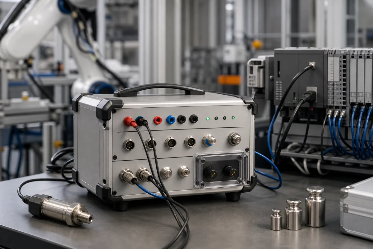
Portable calibration module for load cells and 4–20 mA loops on production lines
Portable calibration units · strain-gauge load cells in mV/V, 4–20 mA loops, simulators and handheld readers for production lines
A portable calibration module here means a carried unit that injects or reads the signals between a machine's sensors and its controller: millivolt-per-volt signals from strain-gauge load cells and 4–20 mA loop currents from transmitters. Before asking for prices, decide which signal you must check, whether the unit must simulate a sensor or read a real one, and how many channels and what accuracy the check needs.
Portable calibration units, load-cell simulators and handheld multi-channel readers used to check strain-gauge load cells, force and pressure sensors and 4–20 mA loops on production lines. PLC-based controllers, motion control and the modules that make up a control system are covered on the Industrial control systems page; laboratory calibration standards and laser alignment modules are outside this page.
CNFX editorial research · Sources checked October 12, 2026 · 3 sources
Load Cell Central's PVS-11 load-cell simulator supplies millivolt signals from 0 to 3 mV/V and is described as used for calibrating scale indicators, troubleshooting and verifying indicator setup; it can stand in for any pressure, torque or force load cell with a millivolt output. [2]
The PVS-11 has two ranges of vernier adjustment and a fixed zero offset of 0.25 mV/V, and it can simulate the power draw of one, two, three, four or eight 350 Ω load cells so an indicator's excitation supply can be tested. [2] Editorial calculation: four 350 Ω bridges in parallel present 87.5 Ω, so at 5 V excitation they draw about 57 mA; eight present 43.75 Ω and draw about 114 mA.
To read real sensors in place, Brans' HK701 handheld reader takes a 0 to 3 mV/V differential input from resistance strain-gauge load cells, drives one to four load cells per channel on up to ten independent channels, excites at 5 V DC and converts at 200 to 1920 Hz with a minimum input of 0.6 µV per division; Brans states it was designed to avoid repeated removal of strain sensors for calibration on automated lines. [3]
Editorial calculation: a load cell rated 2 mV/V excited at 5 V gives 10 mV at full load; spread over the HK701's maximum 10,000 display divisions that is 1 µV per division, above its 0.6 µV/d minimum input. [3] Check the same arithmetic with your cell's rated output before choosing the division count.
Give the supplier the sensor type and rated output (mV/V), bridge resistance, number of cells per channel, excitation voltage, number of channels, sample rate and whether you need simulation, reading or both.
02
Check a 4–20 mA loop by sourcing, simulating and reading
Fluke's 709 precision loop calibrator sources, simulates and reads mA, reads with loop power, and reads volts, over 0 to 24 mA and 0 to 30 V DC, with 1 µA resolution on mA and an accuracy of 0.01% ± 2 counts on all ranges at 23 ± 5 °C. [1]
Fluke lists 24 V DC loop power with an mA measure mode of -25% to 125%, includes a selectable 250 Ω resistor for HART communication, and lists a stability of 20 ppm of full scale per °C outside 18 to 28 °C, an operating range of -10 to 55 °C and 10 to 95% non-condensing humidity. [1]
Editorial calculation: at a 20 mA reading, 0.01% is 2 µA and two counts at 1 µA resolution add 2 µA, so the stated accuracy is ±4 µA, or 0.025% of a 16 mA (4–20 mA) span. [1] Compare that with the tolerance of the transmitter or analog input card you are checking.
03
Choose between simulating and reading
The three reviewed units cover different checks; this comparison uses only their published data.
Calibration weights, as in the photograph, load a real sensor so a reader can be compared with a known force; they are a separate purchase and need their own certificates.
Unit
Check it performs
Published figures
Source
Load-cell simulator (PVS-11)
Replaces the sensor to test the indicator and its excitation.
0–3 mV/V; 0.25 mV/V zero offset; load of 1–8 × 350 Ω cells.
This company lists a portable calibration unit category with a multi-channel load-cell reader.
Hefei Brans Measuring And Controlling Technology Co., Ltd.
Manufacturing site to be confirmed for the order
Lists a portable calibration unit category, including the HK701 ten-channel handheld reader for strain-gauge load cells, alongside load cells and force sensors.
Explore company information and manufacturing capabilities, then discuss the scope of your project with a relevant supplier.
Share this page
Compiled and source-reviewed by the CNFX editorial team.
Each manufacturer above links to the page on that company's own website where the product is listed, with the date we checked it. How we source and review
· Page last updated 13 October 2026
Buyer questions
What does a load-cell simulator do?
Load Cell Central's PVS-11 supplies 0 to 3 mV/V signals to calibrate and troubleshoot indicators and can simulate the draw of up to eight 350 Ω cells. [2]
How accurate is a precision mA loop calibrator?
Fluke's 709 states 0.01% ± 2 counts on all ranges at 23 ± 5 °C, with 1 µA resolution over 0 to 24 mA. [1]
Can load cells be checked without removing them?
Brans' HK701 reads up to ten channels of installed strain-gauge load cells at 0 to 3 mV/V for that purpose. [3]
Sources and what still needs a direct check
Sources checked 2026-10-12. Fluke, Load Cell Central and Brans are makers describing their own instruments; figures are their published specifications, not independent tests.