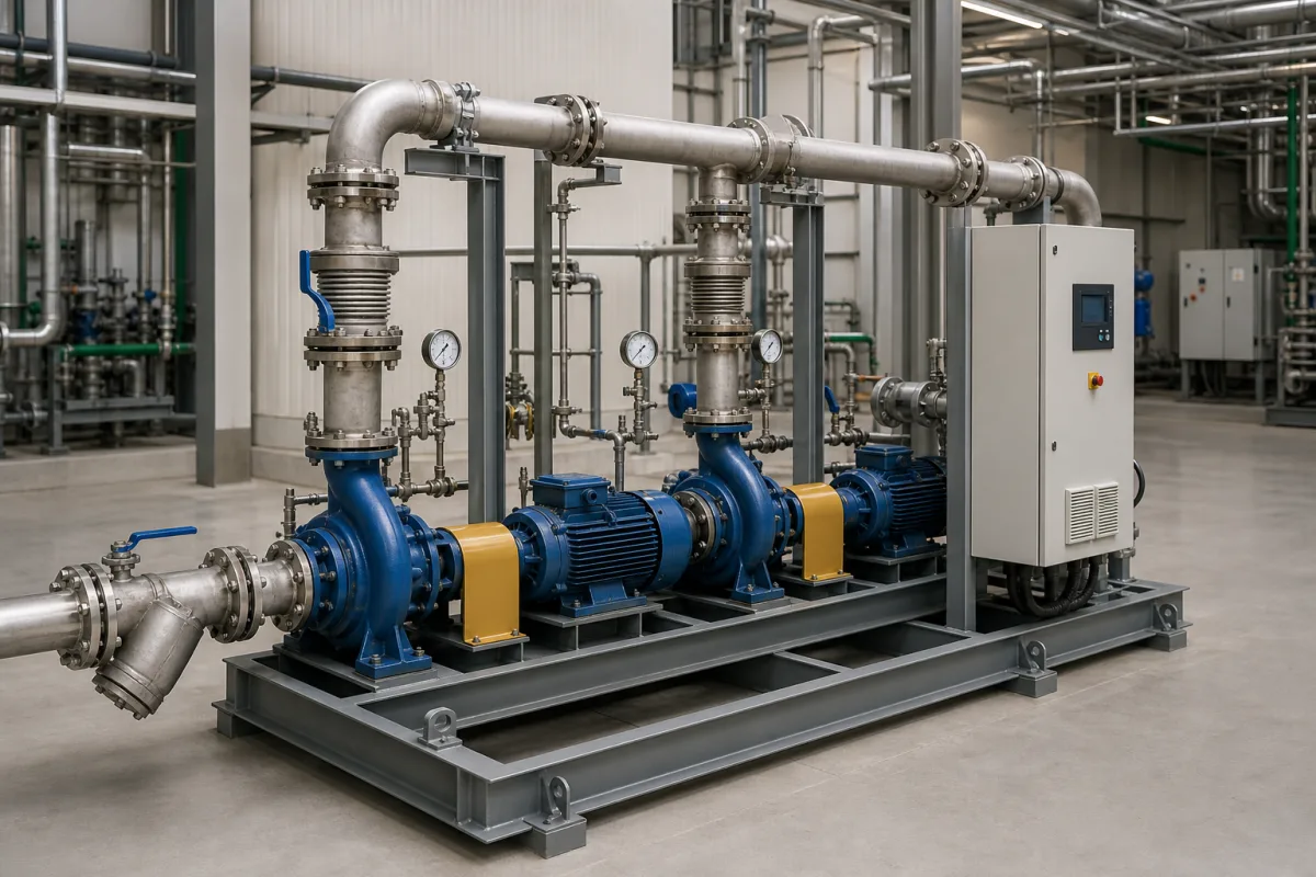
Pumping system (skid-mounted package of two or more centrifugal pumps with valves, strainer, headers and controller on one frame)
Skid-mounted centrifugal pumping systems · duty/standby or parallel pumps on a common frame, check and isolation valves, suction strainer, gauges, headers and pre-wired controller, NPSH and parallel-operation checks
A pumping system here is a package built on one base frame: two or more centrifugal pump sets (pump and motor on a baseplate), suction and discharge headers, a suction strainer, check and isolation valves, gauges and a pre-wired controller, delivered ready to bolt down and connect. Ask three things first: what flow and head the duty point needs and whether pumps run duty/standby or in parallel, whether the suction side gives enough NPSH, and which valves, instruments and controls the skid must carry.
Skid-mounted pumping systems with two or more centrifugal pump sets, headers, valves, strainers, instruments and controllers for process, utility and fire water service. Continuous flow reactors for pharmaceutical synthesis, including their feed pumps, are covered on the Continuous flow reactor for pharmaceutical synthesis page; metering pump feed skids for continuous reactors are covered on the Reagent feed system (metering pump skid) page; single loose pumps, nitrogen pumping units and vacuum pumping systems are outside this page.
CNFX editorial research · Sources checked October 12, 2026 · 5 sources
KSB's pump lexicon explains that when two centrifugal pumps run in parallel, "the flow rate Q I+II is the sum of the flow rates of the individual pumps at the same head", and the actual operating point is where the combined pump curve meets the system curve. Each pump "must be secured with its own check valve", and pumps in parallel run without problems if their curves are stable and their shut-off heads are the same or nearly so; if shut-off heads differ, the weaker pump is pushed towards shut-off, and with unstable curves the pump with the lower shut-off head may not open its check valve and must be started first. KSB adds that if parallel operation is not specified, a double-suction pump can be simpler and cheaper than two separate pumps. [1]
KSB defines a pump set as "a unit comprising the drive and the centrifugal pump", and the baseplate as the joint base for pump and drive which, once aligned, should be protected against piping forces and moments. [3][4]
Editorial note: two identical pumps that each give 50 m³/h at a given head give 100 m³/h only at that same head; on a real system curve the combined flow is lower, so plot both curves before choosing duty/standby or parallel duty. The figures are an assumed example. [1]
Give the skid builder the liquid and temperature, duty flow and head (and range), number of pumps and arrangement (duty/standby, duty/assist, parallel), suction conditions and NPSH available, pump type and materials, motor rating and supply, speed control, valves (isolation, check), strainer type and mesh, instruments, controller functions (alternation, changeover on fault, alarms), skid size and lifting points, piping connection sizes and standards, paint and approvals.
02
Check NPSH and fit out the skid
KSB states that to avoid cavitation the pressure upstream of the impeller must exceed the liquid's vapour pressure by a specified margin, assessed by comparing NPSH available in the system (NPSHA) with NPSH required by the pump (NPSHR); NPSHA includes head losses from entry, valves and fittings, and NPSHR must be given with its cavitation criterion, such as the 3% head drop (NPSH3). [2] Strainers and valves on a skid's suction side count among those losses.
Fike's DuraQuench pump skid shows a factory-built package: a centrifugal pump and motor with a pre-wired controller, a stainless steel suction basket strainer that "prevents debris from entering the pump impeller" and lifts out for cleaning, suction and discharge pressure gauges, isolation valves on the discharge and test header outlets and a pressure regulating loop, all "factory assembled and securely mounted on a steel frame" and tested so that only skid mounting, power, monitoring and pipe connections remain on site. It lists capacities of 53, 75, 111 and 133 gpm (200, 284, 420 and 503 L/min) with 2 or 3 in suction flanges and estimated shipping weights of about 546 to 854 kg, and notes that systems with a jockey pump are not FM approved. [5]
Editorial conversion: 200 L/min is 12 m³/h and 503 L/min about 30.2 m³/h. [5]
03
From suction flange to discharge header: what sits on the skid
Read the skid in flow order: the strainer and suction gauge protect and watch the pump inlet, and KSB requires each pump running in parallel to have its own check valve. [1][5]
Flow, head, NPSH and connection data a skid builder quotes against
Flow and head fix the pump size, but the NPSH line decides whether that pump survives on your suction; the fire-skid figures show the weight and flange sizes a small package reaches.
Explore company information and manufacturing capabilities, then discuss the scope of your project with a relevant supplier.
Share this page
Compiled and source-reviewed by the CNFX editorial team.
Each manufacturer above links to the page on that company's own website where the product is listed, with the date we checked it. How we source and review
· Page last updated 13 October 2026
Buyer questions
How is this different from a continuous flow reactor?
This page covers skid-mounted centrifugal pump packages; continuous flow reactors for pharmaceutical synthesis are on their own page. [1][5]
Do two pumps in parallel double the flow?
KSB says flows add at the same head, but the operating point is where the combined curve meets the system curve. [1]
Why does each pump need a check valve?
KSB states that each pump in parallel must be secured with its own check valve. [1]
What does NPSH mean for the skid?
KSB explains that NPSH available in the system must exceed the NPSH required by the pump to avoid cavitation. [2]
Sources and what still needs a direct check
Sources checked 2026-10-12. KSB's centrifugal pump lexicon explains parallel operation, NPSH, pump sets and baseplates; Fike publishes its DuraQuench pump skid data sheet.