Editorial Technical Reference

Carriage (Slider Block)

This page explains how Carriage (Slider Block) is classified within Machinery and Equipment Manufacturing. Technical values and manufacturer relationships are research references; confirm the current specification and supplier evidence for each order.

Technical Definition & Core Assembly

A precision component that moves along a linear guide rail, providing mounting points for loads and transferring motion.
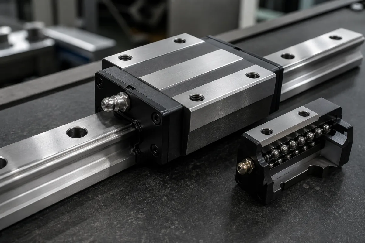
Representative product image. Confirm appearance and specifications with the manufacturer.

Product Specifications

Technical details and manufacturing context for Carriage (Slider Block)

Definition
The carriage, also known as a slider block, is a critical component within a linear motion system. It houses the rolling elements (balls or rollers) and interfaces with the linear guide rail, enabling smooth, low-friction linear movement. It serves as the mounting platform for workpieces, tools, or other machine elements, translating the motion from the drive mechanism into precise linear displacement. The carriage is typically driven by a lead screw, ball screw, belt, or linear motor attached to it, converting rotational or linear force from the drive into precise linear motion of the mounted load. The carriage operates by containing recirculating rolling elements (balls or rollers) within its internal raceways. As it moves along the linear guide rail, these elements roll between the carriage and the rail's raceway, minimizing friction. The carriage is typically driven by a lead screw, ball screw, belt, or linear motor attached to it, converting rotational or linear force from the drive into precise linear motion of the mounted load. Materials commonly used include carbon steel, stainless steel, and aluminum alloy. Key parameters include width (15–60 mm), length (30–120 mm), height (10–40 mm), dynamic load capacity (5–50 kN per ISO 14728-1), static load capacity (10–80 kN per ISO 14728-1), repeatability (±0.005–±0.02 mm per ISO 230-2), maximum speed (2–5 m/s), operating temperature (-40–85 °C), material (GCr15 per GB/T 18254), and weight (0.2–5 kg). These values are reference ranges and must be verified with the manufacturer for specific models. The carriage is selected based on rail width, load requirements, precision class, and environmental conditions. Proper installation, lubrication, and sealing are essential for reliable operation. Regular inspection for wear, noise, or increased friction can indicate maintenance needs. Failure to maintain may lead to reduced accuracy or premature failure. Always consult the supplier for model-specific specifications and standards compliance.
Working Principle
The carriage operates by containing recirculating rolling elements (balls or rollers) within its internal raceways. As it moves along the linear guide rail, these elements roll between the carriage and the rail's raceway, minimizing friction. The carriage is typically driven by a lead screw, ball screw, belt, or linear motor attached to it, converting rotational or linear force from the drive into precise linear motion of the mounted load.
Common Materials
Carbon Steel, Stainless Steel, Aluminum Alloy
Technical Parameters
ParameterTypical rangeNotes & selection driver
Width15–60 mmMatches rail width; wider provides higher load capacity.
Length30–120 mmDetermines mounting hole spacing and load distribution.
Height10–40 mmAffects center of gravity and clearance requirements.
Dynamic Load Capacity5–50 kNMaximum load for rated life of 100 km.ISO 14728-1
Static Load Capacity10–80 kNMaximum load without permanent deformation.ISO 14728-1
Repeatability±0.005–±0.02 mmTighter for high-precision applications.ISO 230-2
Maximum Speed2–5 m/sLimited by lubrication and seal design.
Operating Temperature-40–85 °COutside range may require special seals or lubrication.
MaterialGCr15Bearing steel; other grades available on request.GB/T 18254
Weight0.2–5 kgDepends on size and material.

Ranges are indicative industry figures for RFQ preparation, not a supplier commitment. Confirm every value and standard with the legal manufacturer before ordering.

Components / BOM
  • Carriage Body
    The main structural block that houses internal components and provides mounting holes for the load.
    Material: Carbon Steel or Aluminum Alloy
  • End Seals / Wipers Part
    Seals attached to the ends of the carriage to prevent contamination (dust, chips) from entering and to retain lubrication.
    Material: Synthetic Rubber (NBR, FKM)
  • Ball Retainer / Cage Part
    A component inside the carriage that spaces and guides the recirculating balls, ensuring smooth circulation and preventing ball-to-ball contact.
    Material: Resin (POM) or Stainless Steel
  • Lubrication Fitting Part
    A grease nipple or oil port for introducing lubricant into the carriage's internal raceways.
    Material: Steel
  • Recirculating Balls
    The rolling elements that carry the load between carriage and rail.

Industry Taxonomies & Aliases

Commonly used trade names and technical identifiers for Carriage (Slider Block).

Applied To / Applications

This component is essential for the following industrial systems and equipment:

Industrial Ecosystem & Supply Chain Structure

Complementary Systems
Downstream Applications
Specialized Tooling

Application Fit & Sizing Matrix

Operational Limits
pressure: Max 50 MPa static load capacity, dynamic loads dependent on speed and acceleration
other spec: Max velocity: 5 m/s, acceleration: 50 m/s², lubrication interval: 1000 km travel distance
temperature: -40°C to +85°C
Media Compatibility
✓ Industrial machinery environments (clean to moderate contamination) ✓ Precision automation systems ✓ CNC machine tool applications
Unsuitable: High-concentration abrasive slurry or corrosive chemical immersion without protective seals
Sizing Data Required
  • Maximum load (static and dynamic) in Newtons
  • Required travel length and mounting configuration
  • Operating speed/acceleration profile and duty cycle

Reliability & Engineering Risk Analysis

Failure Mode & Root Cause
Excessive wear and scoring
Cause: Inadequate lubrication leading to metal-to-metal contact, contamination from abrasive particles, or misalignment causing uneven load distribution
Fatigue cracking and fracture
Cause: Cyclic loading beyond design limits, material defects, stress concentrations at mounting points, or thermal expansion/contraction stresses
Maintenance Indicators
  • Audible grinding, scraping, or knocking noises during operation
  • Visible scoring marks, metal flakes in lubricant, or excessive play/movement beyond specifications
Engineering Tips
  • Implement precision alignment during installation and regular alignment checks to ensure even load distribution across the sliding surface
  • Establish a proactive lubrication management program with proper lubricant selection, contamination control, and scheduled replenishment based on operating conditions

Indicative industry ranges for design and RFQ preparation. Confirm the exact figures and applicable standard with the manufacturer before specifying.

Compliance & Manufacturing Standards

Applicable Standards
ANSI B4.1-1967 (R2009) - Preferred Limits and Fits for Cylindrical Parts

Quoted from the published standard.

Manufacturing Precision
  • Bore diameter: +/-0.01mm
  • Parallelism of mounting surfaces: 0.05mm per 100mm
Quality Inspection
  • Dimensional verification with CMM (Coordinate Measuring Machine)
  • Hardness testing using Rockwell C scale

Manufacturers of Carriage (Slider Block)

Manufacturer profiles associated with Carriage (Slider Block).

Sourcing Carriage (Slider Block) from China?
Tell us your specification and target quantity — we will match it against manufacturer records and come back with the factories that fit.
Request manufacturers We manufacture this

Manufacturer listings support early research and capability understanding. They are not certification, ranking, or transaction guarantees.

Technical documentation
Request current drawings, revision history, and a signed specification sheet.
Manufacturing capability
Verify equipment lists, process limits, capacity, and representative production evidence.
Inspection readiness
Confirm test methods, calibrated equipment, sampling plans, and traceable reports.
Supplier transparency
Check the legal entity, factory address, ownership, certifications, and direct contacts.

CNFX does not score or rank suppliers. Buyers must verify all claims and documents with the legal manufacturer before ordering.

Supply Chain Compatible Machinery & Devices

Heavy-Duty CNC Plasma Cutting Machine

The Heavy-Duty CNC Plasma Cutting Machine is a standalone industrial device designed for cutting conductive metals such as steel, stainless steel, aluminum, and copper alloys.

Explore Specs →
Automated Powder Coating System

Integrated industrial system for applying dry powder coatings to metal substrates.

Explore Specs →
Centrifugal Pump Impeller

The centrifugal pump impeller is a critical rotating component that converts mechanical energy from the motor into kinetic energy in fluid systems.

Explore Specs →
High-Precision CNC Laser Cutting Machine

Computer-controlled industrial machine using focused laser beams to cut sheet metal with micron-level accuracy.

Explore Specs →

Frequently Asked Questions

What is the function of a carriage in a linear motion system?

The carriage, or slider block, moves along a linear guide rail and provides a mounting platform for loads. It houses rolling elements that reduce friction, enabling smooth and precise linear movement.

What materials are commonly used for carriages?

Common materials include carbon steel, stainless steel, and aluminum alloy. The material affects strength, corrosion resistance, and weight. The specific grade, such as GCr15 for bearing steel, should be confirmed with the manufacturer.

How do I select the right carriage for my application?

Consider the rail width, required load capacity (dynamic and static), precision (repeatability), speed, operating temperature, and environmental factors. Verify all parameters with the manufacturer for your specific model.

What maintenance does a carriage require?

Regular lubrication and inspection for wear, noise, or increased friction are essential. Follow the manufacturer's guidelines for lubrication intervals and seal condition. Replace worn components to maintain accuracy and prevent failure.

Data Basis

Editorial classification, named public sources where available, and source-reviewed manufacturer records.

Preliminary Technical Classification
This page supports structured research, RFQ preparation, and supplier evaluation. It does not replace buyer-led supplier qualification, standards review, or technical approval.
Buyer enquiry

Request manufacturing insight for Carriage (Slider Block)

Ask for use case, specification boundaries, supplier type, and RFQ preparation information for this product.

Where it goes
Straight to the CNFX editorial desk, and to the manufacturer if this product is linked to a claimed profile. Nothing is broadcast to a supplier list.
Your details stay here
We do not sell or rent enquiry data, and we do not add you to a mailing list. Used only to answer this request.
No commission, no middleman
CNFX is a directory. We take no cut of any order and never negotiate on a supplier's behalf.
What we don't claim
A listing is not an endorsement. Qualify every supplier and verify every figure yourself before ordering.

Your business information is used only to process this request.

Thank you! Your message has been sent. We'll respond within 1–3 business days.
Sorry, we couldn't send your message. Please try again, or email us at contact@cnfx.com.

Need to Manufacture Carriage (Slider Block)?

Compare manufacturer profiles with relevant product and process capability.

Previous Product
Capping Head
Next Product
Carrier Platform
Get QuotesChat