Editorial Technical Reference

Clamping System

This page explains how Clamping System is classified within Machinery and Equipment Manufacturing. Technical values and manufacturer relationships are research references; confirm the current specification and supplier evidence for each order.

Technical Definition & Core Assembly

A mechanical system that securely holds aluminum profiles in position during cutting operations to ensure precision and safety.

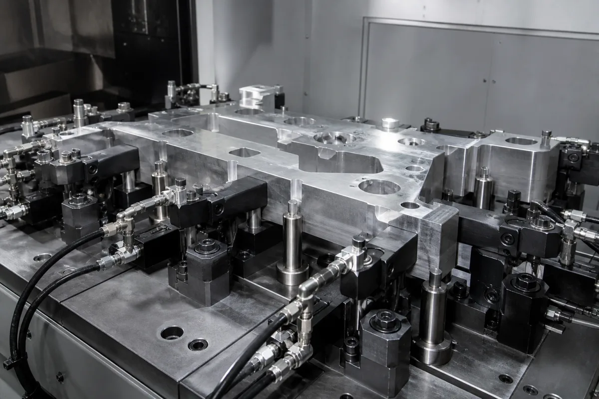
Representative product image. Confirm appearance and specifications with the manufacturer.

Product Specifications

Technical details and manufacturing context for Clamping System

Definition
The clamping system is a critical component of aluminum profile cutting machines that provides stable fixation of workpieces during the cutting process. It prevents movement, vibration, or slippage of aluminum profiles, ensuring accurate cuts, maintaining dimensional tolerances, and protecting both the machine and operator from potential hazards caused by unstable workpieces. The system typically uses mechanical, pneumatic, or hydraulic force to apply pressure through clamping jaws or fixtures onto the aluminum profile. This creates sufficient friction and holding force to counteract cutting forces and vibrations, maintaining the workpiece in a fixed position relative to the cutting tool throughout the operation. Key parameters include clamping force (5–50 kN), clamping accuracy (repeatability ±0.05–0.1 mm), profile width capacity (20–400 mm), and profile height capacity (20–200 mm). Pneumatic systems operate at 6–8 bar, while hydraulic systems operate at 100–200 bar. Materials used include steel, aluminum alloy, and hardened tool steel for jaws (e.g., 42CrMo4, HRC 50–55). The system is designed for a duty cycle of 100% at rated force and a service life of at least 1,000,000 cycles under normal maintenance. Operating temperature range is 0–60 °C. Mounting interfaces include T-slots or bolt patterns (e.g., M12 bolts, 100 mm grid). Relevant standards include ISO 12100, ISO 230-2, ISO 8573-1, ISO 4413, IEC 60068-2-1, IEC 60529, DIN EN ISO 4957, EN 755-2, ISO 3601-1, DIN 650, ISO 1217, ISO 11202, and ISO 19973-1. These standards serve as procurement and verification references; they do not imply certification or compliance of any specific product. Always verify model-specific values and standards with the legal manufacturer or supplier.
Working Principle
The clamping system applies force via mechanical, pneumatic, or hydraulic actuation to clamping jaws or fixtures that contact the aluminum profile. The force generates friction and holding force that counteracts cutting forces and vibrations, keeping the workpiece stationary relative to the cutting tool. Pneumatic systems use compressed air at 6–8 bar, while hydraulic systems use oil at 100–200 bar. The jaws are made of hardened tool steel to resist wear and deformation. The system is designed to operate within a temperature range of 0–60 °C and withstand vibrations up to 5 g. Proper surface condition of the profile (clean, dry, free of oil or chips) is essential for maintaining friction and preventing slippage.
Common Materials
Steel, Aluminum alloy, Hardened tool steel
Technical Parameters
ParameterTypical rangeNotes & selection driver
Clamping force5–50 kN5–50 kN — Depends on profile size and cutting force; higher force for larger profiles.
Clamping accuracy (repeatability)±0.05–0.1 mm±0.05–0.1 mm — Positioning repeatability of the clamping jaws.
Profile width capacity20–400 mm20–400 mm — Range of aluminum profile widths that can be securely clamped.
Profile height capacity20–200 mm20–200 mm — Range of profile heights accommodated.
Operating pressure (pneumatic)6–8 bar6–8 bar — For pneumatic clamping systems; outside this range may cause insufficient force or seal failure.
Operating pressure (hydraulic)100–200 bar100–200 bar — For hydraulic systems; higher pressure for higher force.
Clamping jaw materialHardened tool steel (e.g., 42CrMo4, HRC 50–55)Hardened tool steel (e.g., 42CrMo4, HRC 50–55) — Jaws must resist wear and deformation.
Body materialSteel (e.g., S355JR) or aluminum alloy (e.g., 6061-T6)Steel (e.g., S355JR) or aluminum alloy (e.g., 6061-T6) — Aluminum for lightweight, steel for rigidity.
Seal materialNBR or FKM (Viton)NBR or FKM (Viton) — For pneumatic/hydraulic cylinders; FKM for higher temperature or chemical resistance.
Operating temperature range0–60 °C0–60 °C — Outside this range, seals may fail or lubricants degrade.
Duty cycle100% at rated force %100% at rated force — Continuous operation without overheating or fatigue failure.
Service life≥1,000,000 cycles≥1,000,000 cycles — Under normal maintenance and within specified operating conditions.
Mounting interfaceT-slots or bolt pattern (e.g., M12 bolts, 100 mm grid)T-slots or bolt pattern (e.g., M12 bolts, 100 mm grid) — Must match standard machine tables.
Air consumption (pneumatic)0.5–2.0 L/min per clamp at 6 bar L/min0.5–2.0 L/min per clamp at 6 bar — Depends on cylinder size and cycle rate.
Hydraulic oil flow (hydraulic)5–20 L/min5–20 L/min — Required for hydraulic actuation.
Ambient temperature0–60 °C0–60 °C — Outside this window: Seals may harden or soften, causing leaks or reduced clamping force.
Air supply pressure (pneumatic)6–8 bar6–8 bar — Outside this window: Below 6 bar: insufficient clamping force; above 8 bar: seal damage or excessive wear.
Hydraulic pressure (hydraulic)100–200 bar100–200 bar — Outside this window: Below 100 bar: insufficient force; above 200 bar: component failure or leakage.
Cutting vibrationUp to 5 g (acceleration)Up to 5 g (acceleration) — Outside this window: Higher vibration may cause jaw slippage or loosening.
Profile surface conditionClean, dry, free of oil or chipsClean, dry, free of oil or chips — Outside this window: Contaminants reduce friction, leading to workpiece movement.

Ranges are indicative industry figures for RFQ preparation, not a supplier commitment. Confirm every value and standard with the legal manufacturer before ordering.

Components / BOM
  • Clamping Jaws Part
    Direct contact surfaces that grip the aluminum profile
    Material: Hardened steel
  • Actuation Mechanism
    Provides the force to open and close the clamping jaws
    Material: Steel
  • Mounting Base Part
    Secures the clamping system to the cutting machine frame
    Material: Cast iron or steel
  • Pressure Regulation System
    Controls and maintains consistent clamping force
    Material: Various metals and elastomers

Applied To / Applications

This component is essential for the following industrial systems and equipment:

Industrial Ecosystem & Supply Chain Structure

Complementary Systems
Downstream Applications
Specialized Tooling

Application Fit & Sizing Matrix

What Decides the Award
  • What is the maximum clamping force required for your largest profile and cutting operation?
  • What is the required repeatability of jaw positioning for your precision cutting?
  • What actuation type do you prefer: pneumatic, hydraulic, or manual?
  • What are the dimensions of the profiles you need to clamp (width, height)?
  • What is the available utility supply (air pressure, hydraulic power) in your facility?
  • What is the expected cycle rate and duty cycle of the clamping system?
  • What is your budget for initial purchase and maintenance over the system's lifetime?
Failure Modes & Inspection
  • Jaw wear
    Check: Visual inspection for scoring or deformation; measure jaw profile with calipers; replace if wear exceeds 0.5 mm.
  • Seal leakage
    Check: Check for oil or air leaks during operation; perform pressure decay test (e.g., hold pressure for 5 minutes, drop < 1 bar).
  • Loss of clamping force
    Check: Measure clamping force with a force gauge; compare to specified range; check system pressure.
  • Misalignment of jaws
    Check: Use dial indicator to check jaw parallelism and alignment; adjust or replace worn components.
  • Corrosion
    Check: Visual inspection for rust or pitting; ensure protective coatings are intact; replace if structural integrity compromised.

Reliability & Engineering Risk Analysis

Failure Mode & Root Cause
Clamping force degradation
Cause: Wear of clamping surfaces, hydraulic/pneumatic pressure loss, or mechanical component fatigue leading to insufficient holding force
Misalignment or binding
Cause: Accumulation of debris, improper installation, thermal expansion, or structural deformation causing uneven clamping or restricted movement
Maintenance Indicators
  • Visible leakage of hydraulic fluid or air from clamping cylinders/connections
  • Audible hissing from pneumatic systems or grinding/scraping noises during clamping cycles
Engineering Tips
  • Implement regular torque/force verification using calibrated load cells or pressure gauges to ensure clamping specifications are maintained
  • Establish preventive cleaning and lubrication schedules for sliding surfaces and mechanical linkages to reduce wear and prevent contamination buildup

Indicative industry ranges for design and RFQ preparation. Confirm the exact figures and applicable standard with the manufacturer before specifying.

Compliance & Manufacturing Standards

Manufacturing Precision
  • Bore diameter: +/-0.01mm
  • Parallelism of clamping surfaces: 0.02mm per 100mm
Quality Inspection
  • Dimensional verification with CMM (Coordinate Measuring Machine)
  • Hardness testing (Rockwell C scale)

Manufacturers of Clamping System

6 companies list this product among what they make. Company figures are quoted from each company's own website; every card states where the relationship came from.

CPWS®-China Precision Workholding System Inc
Taiwan, CN
Listed on the company's own website · profile compiled by CNFX from public sources
DurmaPress
Anhui, CN
Listed on the company's own website · profile compiled by CNFX from public sources
G-Press (Jiangsu hongdong industrial automation co.,ltd)
Shanghai, CN
Listed on the company's own website · profile compiled by CNFX from public sources
SilverCNC
Beijing, CN
Also makes: Rotary Table
Listed on the company's own website · profile compiled by CNFX from public sources
SMS Machinery
Hubei, CN
Listed on the company's own website · profile compiled by CNFX from public sources
ZhongTie
Jiangsu, CN
Listed on the company's own website · profile compiled by CNFX from public sources

Manufacturer listings support early research and capability understanding. They are not certification, ranking, or transaction guarantees.

Technical documentation
Request current drawings, revision history, and a signed specification sheet.
Manufacturing capability
Verify equipment lists, process limits, capacity, and representative production evidence.
Inspection readiness
Confirm test methods, calibrated equipment, sampling plans, and traceable reports.
Supplier transparency
Check the legal entity, factory address, ownership, certifications, and direct contacts.

CNFX does not score or rank suppliers. Buyers must verify all claims and documents with the legal manufacturer before ordering.

Supply Chain Compatible Machinery & Devices

Heavy-Duty CNC Plasma Cutting Machine

The Heavy-Duty CNC Plasma Cutting Machine is a standalone industrial device designed for cutting conductive metals such as steel, stainless steel, aluminum, and copper alloys.

Explore Specs →
Automated Powder Coating System

Integrated industrial system for applying dry powder coatings to metal substrates.

Explore Specs →
Centrifugal Pump Impeller

The centrifugal pump impeller is a critical rotating component that converts mechanical energy from the motor into kinetic energy in fluid systems.

Explore Specs →
High-Precision CNC Laser Cutting Machine

Computer-controlled industrial machine using focused laser beams to cut sheet metal with micron-level accuracy.

Explore Specs →

Frequently Asked Questions

What is the typical clamping force range for this system?

The clamping force range is 5–50 kN, depending on profile size and cutting force. Higher force is used for larger profiles. Always verify the required force for your specific application with the manufacturer.

What are the operating pressure requirements for pneumatic and hydraulic versions?

Pneumatic systems require 6–8 bar, while hydraulic systems require 100–200 bar. Operating outside these ranges may cause insufficient force or seal failure. Confirm the exact pressure for your model.

What materials are used in the clamping system?

The body is made of steel (e.g., S355JR) or aluminum alloy (e.g., 6061-T6). Clamping jaws are made of hardened tool steel (e.g., 42CrMo4, HRC 50–55). Seals are NBR or FKM (Viton). These materials are selected for rigidity, wear resistance, and compatibility.

What standards apply to this clamping system?

Relevant standards include ISO 12100, ISO 230-2, ISO 8573-1, ISO 4413, IEC 60068-2-1, IEC 60529, DIN EN ISO 4957, EN 755-2, ISO 3601-1, DIN 650, ISO 1217, ISO 11202, and ISO 19973-1. These are reference standards for design, testing, and verification. They do not guarantee compliance of any specific product; verify with the manufacturer.

Data Basis

Editorial classification, named public sources where available, and source-reviewed manufacturer records.

Preliminary Technical Classification
This page supports structured research, RFQ preparation, and supplier evaluation. It does not replace buyer-led supplier qualification, standards review, or technical approval.
Buyer enquiry

Request manufacturing insight for Clamping System

Ask for use case, specification boundaries, supplier type, and RFQ preparation information for this product.

Where it goes
Straight to the CNFX editorial desk, and to the manufacturer if this product is linked to a claimed profile. Nothing is broadcast to a supplier list.
Your details stay here
We do not sell or rent enquiry data, and we do not add you to a mailing list. Used only to answer this request.
No commission, no middleman
CNFX is a directory. We take no cut of any order and never negotiate on a supplier's behalf.
What we don't claim
A listing is not an endorsement. Qualify every supplier and verify every figure yourself before ordering.

Your business information is used only to process this request.

Thank you! Your message has been sent. We'll respond within 1–3 business days.
Sorry, we couldn't send your message. Please try again, or email us at contact@cnfx.com.

Need to Manufacture Clamping System?

Compare manufacturer profiles with relevant product and process capability.

Previous Product
Z-axis Ram/Spindle
Last Product
Get QuotesChat