Editorial Technical Reference

Clamping Unit

This page explains how Clamping Unit is classified within Machinery and Equipment Manufacturing. Technical values and manufacturer relationships are research references; confirm the current specification and supplier evidence for each order.

Technical Definition & Core Assembly

A mechanical assembly in silicone molding machines that securely closes and holds the mold halves together under high pressure during the injection and curing phases.
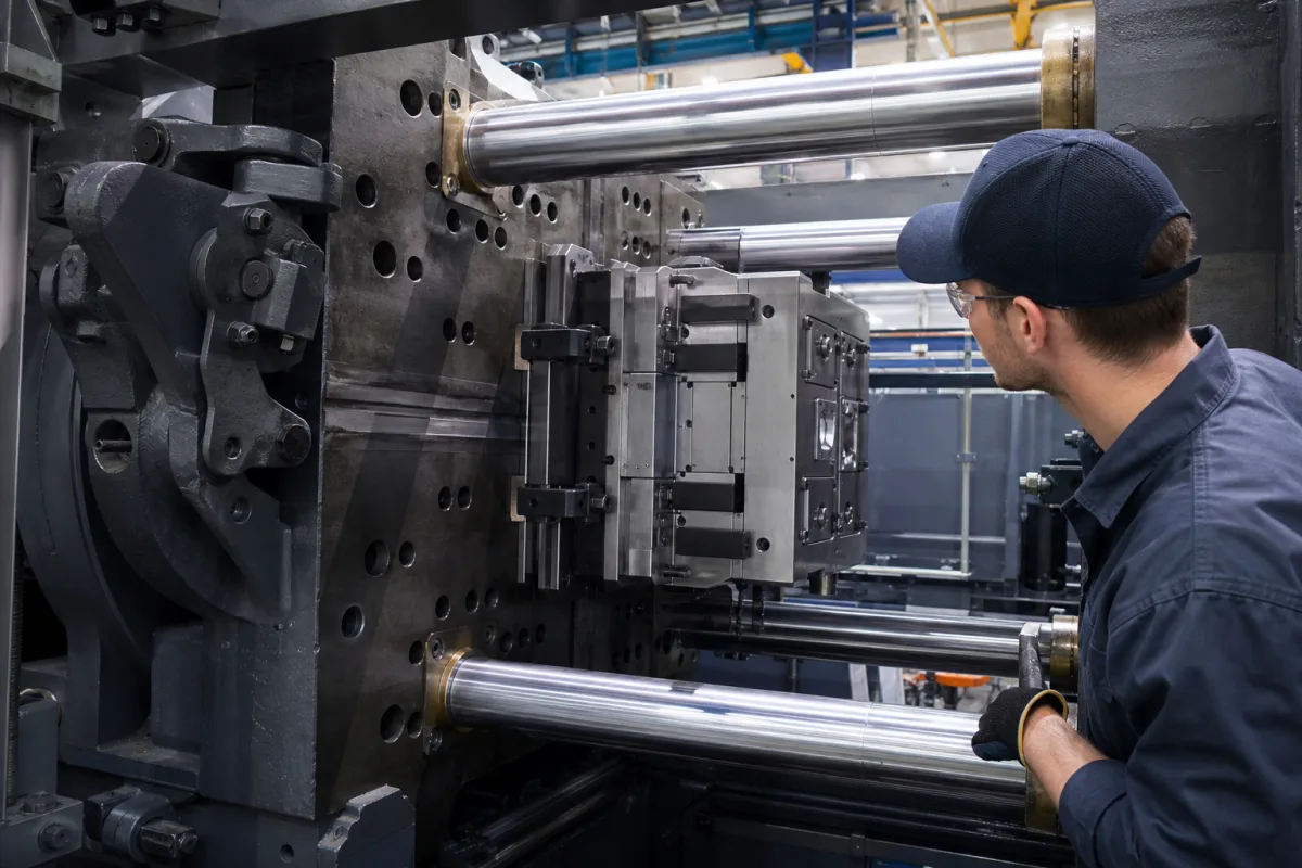
Clamping Unit in a manufacturing environment
Representative product image. Confirm appearance and specifications with the manufacturer.

Product Specifications

Technical details and manufacturing context for Clamping Unit

Definition
The clamping unit is a critical subsystem of a silicone molding machine responsible for securely closing the two mold halves, maintaining them under high clamping force throughout the injection and curing cycle to prevent flash and ensure dimensional accuracy of the molded part. It typically consists of a stationary platen, a moving platen, tie bars, and a clamping mechanism (hydraulic or toggle). The unit operates by moving the moving platen towards the stationary platen to close the mold. A clamping mechanism (hydraulic cylinder or mechanical toggle) then applies and maintains a high force (clamping tonnage) to keep the mold securely closed against the injection pressure of the liquid silicone. After curing, the mechanism releases the force and retracts the moving platen to open the mold for part ejection. The clamping force is a key specification, typically measured in kilonewtons (kN), and must be matched to the projected area of the mold and the injection pressure to prevent mold opening. For selection, verify the required clamping force for your specific mold and machine configuration. The unit interfaces with the injection unit, mold, and machine control system. Maintenance signals include unusual noises, hydraulic leaks, or inconsistent clamping force. Failure boundaries include inability to maintain clamping force, misalignment of platens, or tie bar breakage. Always confirm model-specific values and standards with the legal manufacturer or supplier.
Working Principle
The unit operates by moving the moving platen towards the stationary platen to close the mold. A clamping mechanism (hydraulic cylinder or mechanical toggle) then applies and maintains a high force (clamping tonnage) to keep the mold securely closed against the injection pressure of the liquid silicone. After curing, the mechanism releases the force and retracts the moving platen to open the mold for part ejection.
Common Materials
Alloy Steel
Technical Parameters

What to specify in your RFQ

  • Maximum clamping force (tonnage) the unit can apply. in kN

These are the quantities to specify to the manufacturer when sizing or requesting a quote. The manufacturer's own documentation governs the exact figures and applicable standard.

Components / BOM
  • Stationary Platen Part
    Fixed platen to which one half of the mold is mounted.
    Material: Alloy Steel
  • Moving Platen Part
    Platen that moves to open and close the mold; carries the other mold half.
    Material: Alloy Steel
  • Tie Bars Part
    Guide rods that connect the platens and absorb the clamping force.
    Material: High-Tensile Alloy Steel
  • Clamping Cylinder (or Toggle Mechanism)
    Mechanism (hydraulic or mechanical) that generates the clamping force.
    Material: Alloy Steel

Application & selection

Application Fit & Sizing Matrix

Operational Limits
pressure: Up to 5000 kN clamping force (typical range 1000-5000 kN)
other spec: Mold size: 400x400 mm to 1500x1500 mm, Stroke length: 300-1000 mm, Cycle time: 30-120 seconds
temperature: Ambient to 200°C (mold surface temperature)
Media Compatibility
✓ Liquid Silicone Rubber (LSR) ✓ High-Temperature Thermoplastics ✓ Thermoset Elastomers
Unsuitable: Corrosive chemical environments without protective coatings
Sizing Data Required
  • Mold dimensions and weight
  • Required clamping force (based on projected area and injection pressure)
  • Production cycle time requirements

Risk, maintenance & compliance

Reliability & Engineering Risk Analysis

Failure Mode & Root Cause
Hydraulic cylinder seal degradation
Cause: Contamination of hydraulic fluid leading to abrasive wear, thermal degradation from overheating, or chemical incompatibility with fluid additives
Tie rod fatigue failure
Cause: Cyclic loading exceeding material endurance limit, improper preload during assembly, or stress concentration at thread roots due to poor manufacturing quality
Maintenance Indicators
  • Audible hydraulic hissing or knocking during operation indicating internal leakage or cavitation
  • Visible hydraulic fluid leaks around cylinder seals or excessive play/misalignment in moving components
Engineering Tips
  • Implement condition-based monitoring with vibration analysis on tie rods and hydraulic pressure trending to detect early degradation
  • Establish strict contamination control protocols for hydraulic fluid including regular particle counting and moisture analysis with scheduled fluid replacement

Indicative industry ranges for design and RFQ preparation. Confirm the exact figures and applicable standard with the manufacturer before specifying.

Compliance & Manufacturing Standards

Applicable Standards
ISO 12164-1:2001 (Tool holders for automatic tool changers - Part 1: Shanks and retention knobs) ANSI B5.50-1994 (Specification for Taper and Face Contact Tool Shanks and Retention Knobs) DIN 69893-1:2002 (Tool holders for automatic tool changers - Part 1: Shanks and retention knobs)

Quoted from the published standard.

Manufacturing Precision
  • Bore diameter: +/-0.01mm
  • Parallelism of clamping faces: 0.02mm
Quality Inspection
  • Dimensional verification with CMM (Coordinate Measuring Machine)
  • Hardness testing (Rockwell C scale) for tool steel components
Technical documentation
Request current drawings, revision history, and a signed specification sheet.
Manufacturing capability
Verify equipment lists, process limits, capacity, and representative production evidence.
Inspection readiness
Confirm test methods, calibrated equipment, sampling plans, and traceable reports.
Supplier transparency
Check the legal entity, factory address, ownership, certifications, and direct contacts.

Compare the published product scope and source details, then include your specifications and quantity in an enquiry.

Manufacturers of Clamping Unit

Manufacturer profiles associated with Clamping Unit.

Sourcing Clamping Unit from China?
Tell us your specification and target quantity — we will match it against manufacturer records and come back with the factories that fit.
Request manufacturers We manufacture this

Explore company information and manufacturing capabilities, then discuss the scope of your project with a relevant supplier.

Buyer enquiry

Request manufacturing insight for Clamping Unit

Ask for use case, specification boundaries, supplier type, and RFQ preparation information for this product.

Where it goes
Straight to the CNFX editorial desk, and to the manufacturer if this product is linked to a claimed profile. Nothing is broadcast to a supplier list.
Your details stay here
We do not sell or rent enquiry data, and we do not add you to a mailing list. Used only to answer this request.
No commission, no middleman
CNFX is a directory. We take no cut of any order and never negotiate on a supplier's behalf.
What to include
Share your product specifications, quantity, destination and target delivery date.

Your business information is used only to process this request.

Thank you! Your message has been sent. We'll respond within 1–3 business days.
Sorry, we couldn't send your message. Please try again, or email us at [email protected].

Frequently Asked Questions

What is the primary function of a clamping unit in a silicone molding machine?

The clamping unit securely closes and holds the mold halves together under high pressure during injection and curing, preventing flash and ensuring dimensional accuracy of the molded part.

What are the typical components of a clamping unit?

It typically consists of a stationary platen, a moving platen, tie bars, and a clamping mechanism, which can be hydraulic or toggle type.

How is the required clamping force determined?

The required clamping force depends on the projected area of the mold and the injection pressure. It must be sufficient to keep the mold closed against the injection pressure. Verify the specific value for your application with the manufacturer.

What maintenance signals indicate a problem with the clamping unit?

Unusual noises, hydraulic leaks, or inconsistent clamping force are common signals. Regular inspection and maintenance are recommended to ensure reliable operation.

Related equipment

Applied To / Applications

This component is essential for the following industrial systems and equipment:

Data Basis

Editorial classification, named public sources where available, and source-reviewed manufacturer records.

Preliminary Technical Classification
This page supports structured research, RFQ preparation, and supplier evaluation. It does not replace buyer-led supplier qualification, standards review, or technical approval.

Need to Manufacture Clamping Unit?

Compare manufacturer profiles with relevant product and process capability.

Previous Product
Z-axis Ram/Spindle
Last Product
Get QuotesChat