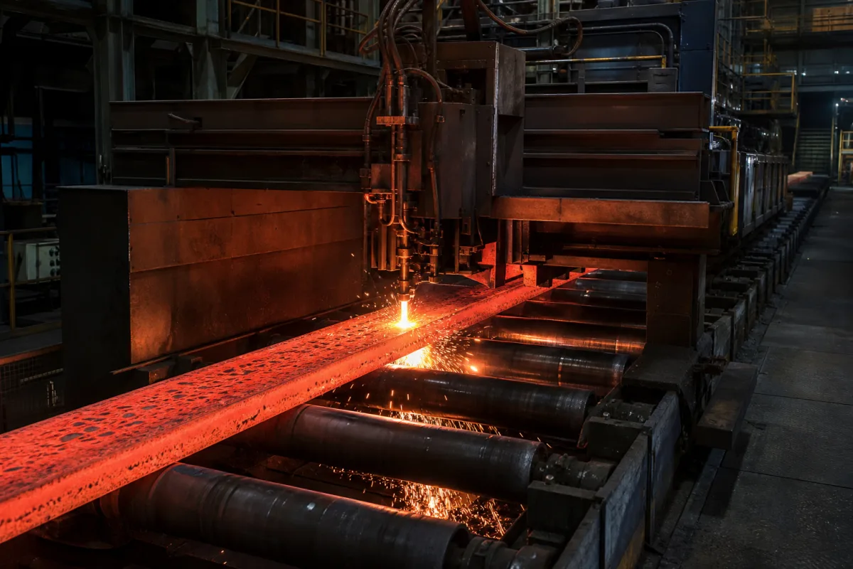
Cutting system for non-ferrous continuous casting: flying saws and billet saw lines
Saw cut-to-length systems for non-ferrous continuous casting · inline flying saws on horizontal billet casters, offline log saws for aluminium billets, synchronisation, support and throughput
On a non-ferrous continuous casting line, the cutting system is the saw, carriage, clamps and conveyors that divide the cast aluminium, copper or brass strand into billets of ordered length. On horizontal casters a flying saw travels with the moving strand and cuts without stopping the cast; on vertical direct-chill casthouses the cooled logs go to a separate billet saw line. Ask three things first: whether the saw must cut inline on a moving strand or offline on stationary logs, what billet diameters, lengths and hourly counts it must handle, and how the saw and its supports avoid disturbing the strand and the mould.
Saw-based cut-to-length systems for continuously or semi-continuously cast non-ferrous billets and logs: inline flying saws on horizontal casters and offline billet saw lines with their conveyors, clamps, length measurement and off-cut handling. Complete non-ferrous casting machines, from melt supply to mould and withdrawal, are covered on the Continuous casting machine for non-ferrous metals page. Oxy-fuel torch cutting machines and hot shears for steel strands are covered on the Torch or shear cutting page; sheet-metal, plastic and food cutting machines are outside this page.
CNFX editorial research · Sources checked October 12, 2026 · 5 sources
Synchronise an inline flying saw with the moving strand
A Novelis patent on horizontal casting and cutting of metal billets, such as aluminium, explains that horizontal casting produces ingot continuously and therefore needs cutting to length that does not interrupt the process. In its design a flying saw on its own carriage and rails waits at its upstream end, accelerates to the speed of the casting conveyor and is synchronised with it before the cut begins; the blade turns at a constant speed, is ramped up as it approaches the billet and ramped down after the cut, and is advanced through the billet by a variable-speed drive against a resistance load that damps the entry and exit and lifts the blade clear if power fails. [1]
After the cut, the patent accelerates the saw carriage and the downstream conveyor relative to the upstream conveyor, the carriage less than the downstream conveyor, so the cut billet separates from the strand by a set gap before the carriage returns. The saw motor and blade run on rails at 45° to the horizontal, moving transverse to the billet. The billet sits on a resilient V-shaped belt and is held by rolling clamps, never fixed solidly to the saw carriage; the patent states that isolating the saw in this way limits low- and high-frequency vibration reaching the solidifying billet surface at the mould and so improves surface quality. [1]
The same document cites earlier designs: a horizontal aluminium billet caster with pinch rolls and a flying saw, a caster linked to a homogenising furnace whose flying saw carries a billet clamp on the saw table, and a rotary saw that turns the billet against the blade. [1] For copper alloys, SMS group lists a flying saw and an exit roller table with separating device in its scope for a four-strand, fully continuous horizontal brass billet caster at Hailiang Metal Europe, Italy. [5]
Give the supplier the metal and alloy, strand count and spacing, billet diameter or section, casting speed, ordered lengths and tolerances, whether the cut is inline or offline, cooling water present at the cut, chip and off-cut handling, and the interface to the caster's withdrawal and control system.
02
Size an offline billet saw line for the casthouse output
Hertwich Engineering describes its circular billet sawing plants as part of automated billet production: after cooling, logs pass over storage conveyors and roller tables to the billet saw and are cut into short or long billets. It lists automated parameter changes for new log batches, log tracking from the homogenising plant to the finished bundle, feed control that limits cutting feed according to rated amperage, and stored cutting parameters for alloys and billet diameters. [2]
For a line at Century Aluminum's Sebree, Kentucky plant, scheduled to go into service in 2024, Hertwich states that the sawing line processes aluminium billets of seven to twelve inches diameter with an hourly capacity of up to 225 short billets of at most 1.60 m or 60 long billets of at most 6.10 m, followed by weighing, stacking with transfer cars and PET strapping. [4]
Editorial calculation: 225 billets × 1.60 m is up to 360 m of billet per hour and 60 × 6.10 m is up to 366 m per hour, about 6 m per minute in either mode; check this against the casthouse's log output, since the published figures are maxima at the stated lengths. [4] SMS group gives 245–400 mm diameter and up to 150,000 t a year for the four-strand brass caster that carries a flying saw, so an inline saw there must cut billets up to 400 mm across on each strand. [5]
03
Compare inline and offline cutting arrangements
Editorial note: the steel strand practice of torch cutting and hot shearing belongs to a different metal and process; for aluminium, copper and brass billets the sources reviewed here describe saws.
Arrangement
How the cut is made
Source
Inline flying saw, horizontal caster
Saw carriage synchronised with the conveyor; blade at 45°; rolling clamps; separation gap after the cut. [1]
Patent
Flying saw on a multi-strand brass caster
Flying saw with exit roller table and separating device. [5]
Supplier reference
Offline circular or band saw line
Cooled logs conveyed to the billet saw; short or long billets; scrap removal. [2][3]
Supplier product page
Flying saw with clamp on the saw table
Clamp travels with the saw table (cited prior design). [1]
Patent background
04
Saw, carriage, clamps and scrap handling on a billet cut-off
Component
Role
Fix in the order
Saw blade and motor
Circular blade at constant speed during the cut. [1][2]
Blade diameter, tooth form, motor power.
Feed drive and resistance load
Advances the blade; damps entry and exit; lifts clear on power loss. [1]
Explore company information and manufacturing capabilities, then discuss the scope of your project with a relevant supplier.
Share this page
Compiled and source-reviewed by the CNFX editorial team.
Each manufacturer above links to the page on that company's own website where the product is listed, with the date we checked it. How we source and review
· Page last updated 13 October 2026
Buyer questions
What is a flying saw on a continuous caster?
A saw on a carriage that accelerates to the strand speed, cuts while travelling with it and returns, so casting does not stop; a Novelis patent describes one for horizontal billet casting. [1]
How many aluminium billets can a saw line cut per hour?
Hertwich states up to 225 short billets of at most 1.60 m or 60 long billets of at most 6.10 m per hour for one 7–12 in billet line. [4]
Do brass horizontal casters use flying saws?
SMS group lists a flying saw and exit roller table with separating device for a four-strand horizontal brass billet caster. [5]
Sources and what still needs a direct check
Sources checked 2026-10-12. The Novelis patent describes an inline flying saw design and cites earlier designs; Hertwich Engineering and SMS group describe their own saw lines and caster scopes. Patents describe inventions, not tested products.