Editorial Technical Reference

CNC Milling Module

This page explains how CNC Milling Module is classified within Machinery and Equipment Manufacturing. Technical values and manufacturer relationships are research references; confirm the current specification and supplier evidence for each order.

Technical Definition & Core Assembly

A modular unit within an Aluminum CNC Machining Cell that performs precision milling operations on aluminum workpieces.
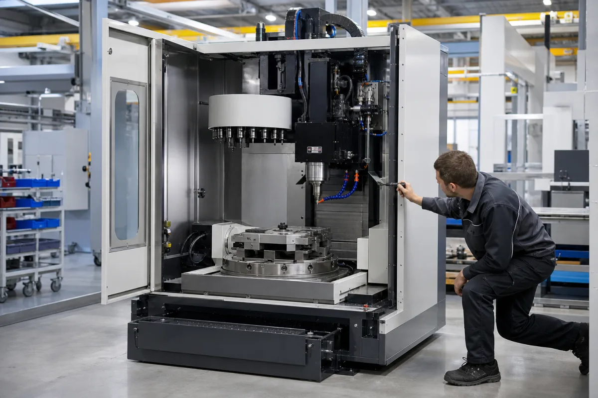
Representative product image. Confirm appearance and specifications with the manufacturer.

Product Specifications

Technical details and manufacturing context for CNC Milling Module

Definition
The CNC Milling Module is a critical component of an Aluminum CNC Machining Cell, specifically designed for subtractive manufacturing processes. It houses the spindle, tool changer, and axis drives necessary to execute programmed milling paths, removing material from aluminum blanks to create complex parts with high dimensional accuracy and surface finish. The module is typically constructed with a cast iron or steel base for rigidity, while aluminum alloy housings reduce weight. It operates within a defined range of spindle speeds (8000–24000 rpm) and spindle power (5.5–15 kW), enabling both high-speed finishing and heavy cutting. Positioning accuracy is specified as ±0.005 to ±0.01 mm, and repeatability as ±0.003 to ±0.005 mm, both referenced to ISO 230-2. Rapid traverse rates range from 20 to 60 m/min, and cutting feed rates from 1 to 15 m/min, affecting cycle times. Axis travel (X/Y/Z) is available in ranges such as 500–2000 / 400–800 / 400–600 mm, defining maximum workpiece size. Tool shanks conform to BT30–BT40 (ISO 7388), and tool magazine capacity ranges from 16 to 40 tools. Coolant pressure is 1.0–6.0 MPa to aid chip evacuation. The module operates in ambient temperatures of 5–45°C, requires a three-phase 380–480 V AC supply (IEC 60038), and weighs between 3000 and 8000 kg. These values are reference ranges; actual specifications must be confirmed with the legal manufacturer for the specific model and application. The module is not a standalone machine but a part of a larger cell, and its performance depends on integration with the cell's controller and auxiliary systems.
Working Principle
The module receives G-code instructions from the cell's central controller. Its servo motors drive linear axes (typically X, Y, Z) to position the workpiece relative to a high-speed rotating spindle. Cutting tools mounted in the spindle engage the aluminum workpiece, shearing away material according to the programmed toolpath to achieve the desired geometry. The tool changer automatically swaps tools from the magazine as needed, and coolant is applied under pressure to control temperature and evacuate chips. The module's control system monitors axis positions and spindle load to maintain accuracy and detect anomalies.
Common Materials
Cast Iron, Steel, Aluminum Alloy (for housings)
Technical Parameters
ParameterTypical rangeNotes & selection driver
Spindle Speed8000–24000 rpmHigher speed for fine finishes; lower for heavy cuts.
Spindle Power5.5–15 kWDetermines material removal rate.
Positioning Accuracy±0.005–±0.01 mmCritical for tight tolerances.ISO 230-2
Repeatability±0.003–±0.005 mmEnsures consistency across parts.ISO 230-2
Rapid Traverse Rate20–60 m/minAffects cycle time.
Cutting Feed Rate1–15 m/minDepends on tool and material.
Axis Travel (X/Y/Z)500–2000 / 400–800 / 400–600 mmDefines maximum workpiece size.
Tool ShankBT30–BT40Compatibility with tooling.ISO 7388
Tool Magazine Capacity16–40 toolsNumber of tools for automatic change.
Coolant Pressure1.0–6.0 MPaHigher pressure improves chip evacuation.
Operating Temperature5–45 °COutside range may affect accuracy.
Rated Power Supply380–480 V ACThree-phase, 50/60 Hz.IEC 60038
Machine Weight3000–8000 kgAffects installation and floor loading.

Ranges are indicative industry figures for RFQ preparation, not a supplier commitment. Confirm every value and standard with the legal manufacturer before ordering.

Components / BOM
  • Spindle Assembly
    Rotates the cutting tool at high speeds to perform the milling operation.
    Material: Steel, Ceramic Bearings
  • Linear Guideways
    Provide precise, low-friction movement for the machine axes (X, Y, Z).
    Material: Hardened Steel
  • Ball Screw Drive
    Converts rotary motion from servo motors into precise linear motion for axis movement.
    Material: Alloy Steel
  • Tool Magazine
    Stores multiple cutting tools and automatically exchanges them with the spindle as required by the program.
    Material: Aluminum Alloy, Steel
  • Servo Motors
    Drive the X, Y and Z axes to the programmed positions.
  • Coolant System
    Delivers cutting fluid under pressure to cool the tool and flush chips.
  • Control System
    Runs the G-code, watches axis position and spindle load, and flags anomalies.

Industrial Ecosystem & Supply Chain Structure

Complementary Systems
Downstream Applications
Specialized Tooling

Application Fit & Sizing Matrix

Operational Limits
pressure: 0.5-1.0 MPa (coolant system)
feed rate: 0.1-10 m/min
temperature: 15-35°C (operating ambient)
spindle speed: 500-12000 RPM
workpiece size: Max 500x500x300 mm
Media Compatibility
✓ 6061 Aluminum Alloy ✓ 7075 Aluminum Alloy ✓ 5083 Aluminum Alloy
Unsuitable: High-silicon aluminum castings (>12% Si)
Sizing Data Required
  • Maximum workpiece dimensions (LxWxH)
  • Required material removal rate (cm³/min)
  • Desired surface finish tolerance (Ra value)

Reliability & Engineering Risk Analysis

Failure Mode & Root Cause
Spindle Bearing Wear
Cause: Inadequate lubrication, contamination from metal chips or coolant, excessive axial/radial loads, or improper preload adjustment leading to increased friction, heat generation, and eventual bearing seizure or excessive runout.
Ball Screw Backlash
Cause: Wear of ball screw nuts or support bearings due to lack of lubrication, contamination ingress, or misalignment, resulting in positional inaccuracy, vibration, and loss of precision in axis movement.
Maintenance Indicators
  • Unusual grinding, whining, or knocking noises from the spindle during operation, indicating bearing wear or misalignment.
  • Visible coolant leakage around spindle seals or axis drives, or excessive vibration felt during milling, suggesting seal failure or mechanical imbalance.
Engineering Tips
  • Implement a strict preventive maintenance schedule for lubrication and filtration: use high-quality, manufacturer-recommended lubricants, regularly replace coolant filters, and monitor lubrication systems to prevent contamination and ensure proper bearing and screw life.
  • Conduct regular alignment checks and thermal compensation calibration: verify spindle and axis alignments periodically, and use thermal sensors or compensation software to account for heat expansion during prolonged operation, maintaining machining accuracy and reducing mechanical stress.

Indicative industry ranges for design and RFQ preparation. Confirm the exact figures and applicable standard with the manufacturer before specifying.

Compliance & Manufacturing Standards

Applicable Standards
ISO 10791-1:2015 (Test conditions for machining centres) ANSI B5.54-2005 (Methods for performance evaluation of CNC machining centres)

Quoted from the published standard.

Manufacturing Precision
  • Positional accuracy: +/-0.005mm
  • Surface finish: Ra 0.8μm
Quality Inspection
  • Laser interferometer calibration test
  • Ball bar test for circular interpolation accuracy

Manufacturers of CNC Milling Module

Manufacturer profiles associated with CNC Milling Module.

Sourcing CNC Milling Module from China?
Tell us your specification and target quantity — we will match it against manufacturer records and come back with the factories that fit.
Request manufacturers We manufacture this

Manufacturer listings support early research and capability understanding. They are not certification, ranking, or transaction guarantees.

Technical documentation
Request current drawings, revision history, and a signed specification sheet.
Manufacturing capability
Verify equipment lists, process limits, capacity, and representative production evidence.
Inspection readiness
Confirm test methods, calibrated equipment, sampling plans, and traceable reports.
Supplier transparency
Check the legal entity, factory address, ownership, certifications, and direct contacts.

CNFX does not score or rank suppliers. Buyers must verify all claims and documents with the legal manufacturer before ordering.

Supply Chain Compatible Machinery & Devices

Hydraulic Press

Industrial machine using hydraulic pressure to compress, form, or assemble materials

Explore Specs →
Heavy-Duty CNC Plasma Cutting Machine

The Heavy-Duty CNC Plasma Cutting Machine is a standalone industrial device designed for cutting conductive metals such as steel, stainless steel, aluminum, and copper alloys.

Explore Specs →
Automated Powder Coating System

Integrated industrial system for applying dry powder coatings to metal substrates.

Explore Specs →
Centrifugal Pump Impeller

The centrifugal pump impeller is a critical rotating component that converts mechanical energy from the motor into kinetic energy in fluid systems.

Explore Specs →

Frequently Asked Questions

What is the typical spindle speed range for this module?

The spindle speed range is 8000–24000 rpm, with higher speeds for fine finishes and lower speeds for heavy cuts. Confirm the exact range for your specific model.

What standards are referenced for positioning accuracy?

Positioning accuracy and repeatability are referenced to ISO 230-2. The stated ranges are ±0.005–±0.01 mm for accuracy and ±0.003–±0.005 mm for repeatability. Always verify compliance with the manufacturer.

What tool shank types are compatible?

The module supports BT30–BT40 tool shanks per ISO 7388. Tool magazine capacity ranges from 16 to 40 tools. Check compatibility with your tooling.

What are the electrical requirements?

The module requires a three-phase 380–480 V AC supply (IEC 60038) at 50/60 Hz. Operating temperature range is 5–45°C. Confirm with the manufacturer for your installation.

Data Basis

Editorial classification, named public sources where available, and source-reviewed manufacturer records.

Preliminary Technical Classification
This page supports structured research, RFQ preparation, and supplier evaluation. It does not replace buyer-led supplier qualification, standards review, or technical approval.
Buyer enquiry

Request manufacturing insight for CNC Milling Module

Ask for use case, specification boundaries, supplier type, and RFQ preparation information for this product.

Where it goes
Straight to the CNFX editorial desk, and to the manufacturer if this product is linked to a claimed profile. Nothing is broadcast to a supplier list.
Your details stay here
We do not sell or rent enquiry data, and we do not add you to a mailing list. Used only to answer this request.
No commission, no middleman
CNFX is a directory. We take no cut of any order and never negotiate on a supplier's behalf.
What we don't claim
A listing is not an endorsement. Qualify every supplier and verify every figure yourself before ordering.

Your business information is used only to process this request.

Thank you! Your message has been sent. We'll respond within 1–3 business days.
Sorry, we couldn't send your message. Please try again, or email us at contact@cnfx.com.

Need to Manufacture CNC Milling Module?

Compare manufacturer profiles with relevant product and process capability.

Previous Product
Z-axis Ram/Spindle
Last Product
Get QuotesChat