Editorial Technical Reference

Combustion System

This page explains how Combustion System is classified within Machinery and Equipment Manufacturing. Technical values and manufacturer relationships are research references; confirm the current specification and supplier evidence for each order.

Technical Definition & Core Assembly

A subsystem within an industrial steam generation system that efficiently burns fuel to produce heat for steam production.

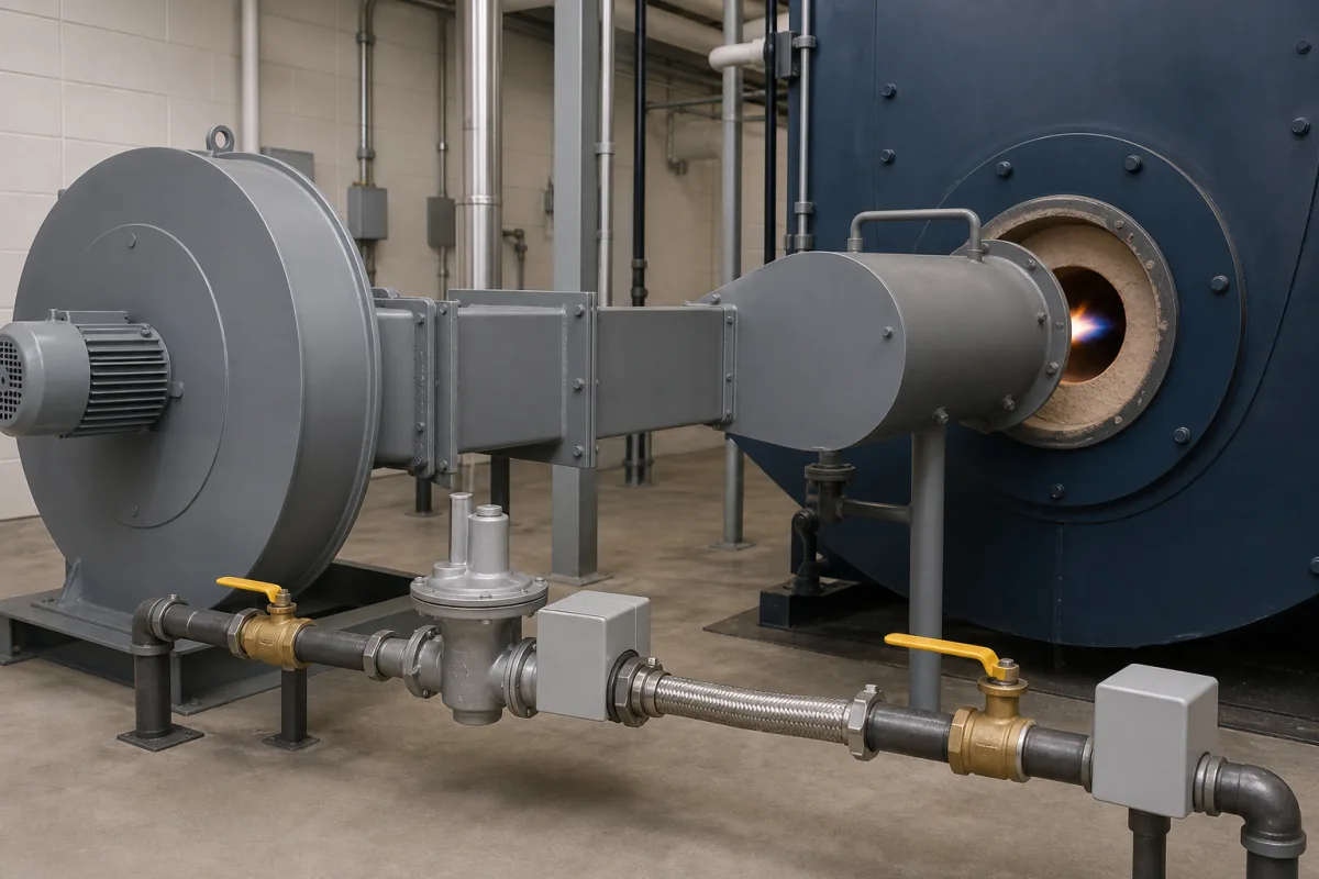
Combustion System in a manufacturing environment
Representative product image. Confirm appearance and specifications with the manufacturer.

Product Specifications

Technical details and manufacturing context for Combustion System

Definition
The combustion system is a critical component of an industrial steam generation system for process heating, responsible for the controlled burning of fuel (such as natural gas, oil, or coal) to generate high-temperature thermal energy. This heat is transferred to a boiler or heat exchanger to produce steam, which is then used for various industrial heating applications. The system ensures efficient fuel-air mixing, stable flame maintenance, and complete combustion to maximize energy output while minimizing emissions. It typically includes a burner, combustion chamber, fuel supply lines, air supply and control dampers, ignition system, flame monitoring, and control instrumentation. The system operates with precise fuel-air ratios to achieve thermal efficiencies in the range of 85–95%, with thermal capacities from 10 to 100 MW. Fuel types include natural gas, LPG, and fuel oil. Fuel consumption ranges from 100 to 1000 Nm³/h, depending on capacity and fuel. Excess air ratio is maintained between 1.1 and 1.3 to balance NOx and CO emissions, with NOx typically 30–80 mg/Nm³ and CO 10–50 mg/Nm³, per EN 267. Operating pressure is 1.0–1.6 MPa, and flue gas outlet temperature is 200–400°C. Control voltage is 24 V DC ±10% (IEC 61131-2), with power consumption of 5–50 kW for fans, pumps, and controls. Materials include refractory lining, stainless steel (SS304/316 per ASTM A240), and heat-resistant alloys. Weight ranges from 500 to 5000 kg, and dimensions vary from 2000×1500×2000 mm to 5000×3000×4000 mm. These values are reference ranges; verify model-specific data with the manufacturer. The system is designed for integration with boiler controls and must be selected based on steam demand, fuel type, and emission limits. Regular maintenance includes checking flame stability, fuel-air ratio, and emission levels. Failure signs include unstable flame, high CO, or excessive NOx. Always confirm standards and performance with the legal manufacturer or supplier.
Working Principle
Fuel and air are introduced into a combustion chamber in precise ratios. An ignition source initiates the combustion reaction. The system controls the flow rates to maintain a stable flame, and the resulting hot combustion gases transfer their heat energy to water tubes or a heat exchanger surface, converting water to steam. Modern systems often include sensors and controllers to optimize the air-fuel ratio for efficiency and emissions control.
Common Materials
Refractory Lining, Stainless Steel, Heat-Resistant Alloys
Technical Parameters
ParameterTypical rangeNotes & selection driver
Thermal Capacity10–100 MWDetermines steam output; match to boiler demand.
Thermal Efficiency85–95 %Higher efficiency reduces fuel cost.ISO 50001
Fuel TypeNG/LPG/FOSelect burner and controls accordingly.
Fuel Consumption100–1000 Nm³/hDepends on thermal capacity and fuel type.
Excess Air Ratio1.1–1.3Lower reduces NOx but increases CO.
NOx Emission30–80 mg/Nm³Regulatory limit; lower is better.EN 267
CO Emission10–50 mg/Nm³High indicates incomplete combustion.EN 267
Operating Temperature200–400 °CFlue gas temperature at outlet.
Control Voltage24 ±10% V DCFor PLC and burner controls.IEC 61131-2
Power Consumption5–50 kWIncludes fans, pumps, controls.
Material GradeSS304/316Corrosion resistance for high temp.ASTM A240
Weight500–5000 kgAffects installation and foundation.
Dimensions (L×W×H)2000×1500×2000–5000×3000×4000 mmSpace requirement for layout.

Ranges are indicative industry figures for RFQ preparation, not a supplier commitment. Confirm every value and standard with the legal manufacturer before ordering.

Components / BOM
  • Burner
    Mixes fuel and air and provides a stable ignition point for combustion.
    Material: Stainless Steel, Ceramic
  • Combustion Chamber
    Enclosed space where the fuel-air mixture is burned, containing the flame and high temperatures.
    Material: Refractory Brick, Insulated Steel
  • Fuel Supply & Control Valve
    Regulates the flow rate and pressure of fuel entering the burner.
    Material: Brass, Stainless Steel
  • Air Blower/Damper
    Supplies and controls the volume of combustion air for mixing with the fuel.
    Material: Steel, Aluminum
  • Ignition System
    Provides the initial spark or pilot flame to start the combustion process.
    Material: Ceramic, Metal Alloys
  • Flame Sensor/Scanner
    Monitors the presence and stability of the flame for safety and control.
    Material: Quartz, Stainless Steel Housing

Industrial Ecosystem & Supply Chain Structure

Complementary Systems
Downstream Applications
Specialized Tooling

Application Fit & Sizing Matrix

Operational Limits
pressure: 0-5 bar (combustion chamber), 0-2 bar (fuel supply)
flow rate: 100-10,000 Nm³/h (air), 10-1,000 kg/h (fuel)
temperature: 800-1600°C (combustion zone), 200-400°C (inlet air)
slurry concentration: Not applicable (solid/liquid fuels handled separately)
Media Compatibility
✓ Natural gas ✓ Fuel oil (No. 2-6) ✓ Pulverized coal
Unsuitable: Chlorinated or halogenated compounds (cause corrosion and emissions issues)
Sizing Data Required
  • Steam production rate (kg/h)
  • Fuel type and heating value (MJ/kg)
  • Required combustion efficiency (%)

Reliability & Engineering Risk Analysis

Failure Mode & Root Cause
Flame impingement
Cause: Incorrect burner alignment or improper air-fuel ratio causing direct flame contact with refractory or heat exchanger surfaces, leading to localized overheating and material degradation.
Thermal fatigue cracking
Cause: Rapid thermal cycling from frequent startups/shutdowns or load changes creating stress concentrations in combustion chamber components, particularly at weld joints and material transitions.
Maintenance Indicators
  • Yellow-tipped or flickering flames instead of steady blue combustion
  • Unusual pulsating or rumbling sounds during operation indicating combustion instability
Engineering Tips
  • Implement continuous oxygen trim control with zirconia probes to maintain optimal excess air levels (typically 2-3% O2) and prevent both incomplete combustion and excessive oxidation
  • Establish a controlled cooldown procedure requiring minimum 30-minute gradual temperature reduction before shutdown to minimize thermal stress on refractory linings and pressure parts

Indicative industry ranges for design and RFQ preparation. Confirm the exact figures and applicable standard with the manufacturer before specifying.

Compliance & Manufacturing Standards

Applicable Standards
ISO 11042-1:1996 - Gas turbine systems - Exhaust gas emission ANSI Z21.1 - Household cooking gas appliances DIN 18840 - Combustion systems for heating boilers

Quoted from the published standard.

Manufacturing Precision
  • Burner nozzle orifice diameter: +/-0.01mm
  • Combustion chamber weld seam alignment: +/-0.5mm
Quality Inspection
  • Leakage pressure test (hydrostatic/pneumatic)
  • Flue gas analysis for CO/NOx emissions

Manufacturers of Combustion System

Manufacturer profiles associated with Combustion System.

Sourcing Combustion System from China?
Tell us your specification and target quantity — we will match it against manufacturer records and come back with the factories that fit.
Request manufacturers We manufacture this

Manufacturer listings support early research and capability understanding. They are not certification, ranking, or transaction guarantees.

Share this page
Technical documentation
Request current drawings, revision history, and a signed specification sheet.
Manufacturing capability
Verify equipment lists, process limits, capacity, and representative production evidence.
Inspection readiness
Confirm test methods, calibrated equipment, sampling plans, and traceable reports.
Supplier transparency
Check the legal entity, factory address, ownership, certifications, and direct contacts.

CNFX does not score or rank suppliers. Buyers must verify all claims and documents with the legal manufacturer before ordering.

Supply Chain Compatible Machinery & Devices

Automated Powder Coating System

Integrated industrial system for applying dry powder coatings to metal substrates.

Explore Specs →
Centrifugal Pump Impeller

The centrifugal pump impeller is a critical rotating component that converts mechanical energy from the motor into kinetic energy in fluid systems.

Explore Specs →
High-Precision CNC Laser Cutting Machine

Computer-controlled industrial machine using focused laser beams to cut sheet metal with micron-level accuracy.

Explore Specs →
Industrial-Grade Hydraulic Cylinder Piston Rod

This industrial-grade piston rod is a precision-ground cylindrical component designed for use in hydraulic cylinders.

Explore Specs →

Frequently Asked Questions

What is the typical thermal capacity range for this combustion system?

The reference range is 10 to 100 MW, but the actual capacity must be matched to the boiler demand and confirmed with the manufacturer for the specific model.

Which fuel types are supported?

The system can operate on natural gas, LPG, or fuel oil. The specific fuel type must be selected based on availability and burner configuration, and verified with the supplier.

What emission standards are referenced?

NOx and CO emissions are referenced to EN 267, with typical ranges of 30-80 mg/Nm³ and 10-50 mg/Nm³ respectively. These are reference values; actual compliance must be verified with the manufacturer.

What are the key maintenance indicators?

Monitor flame stability, excess air ratio, and emission levels. High CO indicates incomplete combustion, while high NOx may require tuning. Regular checks of refractory lining and material integrity are recommended.

Data Basis

Editorial classification, named public sources where available, and source-reviewed manufacturer records.

Preliminary Technical Classification
This page supports structured research, RFQ preparation, and supplier evaluation. It does not replace buyer-led supplier qualification, standards review, or technical approval.
Buyer enquiry

Request manufacturing insight for Combustion System

Ask for use case, specification boundaries, supplier type, and RFQ preparation information for this product.

Where it goes
Straight to the CNFX editorial desk, and to the manufacturer if this product is linked to a claimed profile. Nothing is broadcast to a supplier list.
Your details stay here
We do not sell or rent enquiry data, and we do not add you to a mailing list. Used only to answer this request.
No commission, no middleman
CNFX is a directory. We take no cut of any order and never negotiate on a supplier's behalf.
What we don't claim
A listing is not an endorsement. Qualify every supplier and verify every figure yourself before ordering.

Your business information is used only to process this request.

Thank you! Your message has been sent. We'll respond within 1–3 business days.
Sorry, we couldn't send your message. Please try again, or email us at [email protected].

Need to Manufacture Combustion System?

Compare manufacturer profiles with relevant product and process capability.

Previous Product
Z-axis Ram/Spindle
Last Product
Get QuotesChat