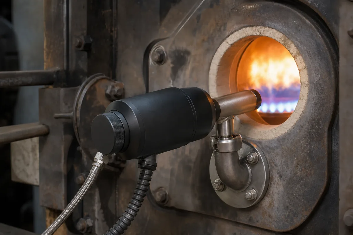
Flame scanners for burner safety · UV tube detection and self-checking shutters, flame failure response time (FFRT), fuels detected, sight pipe and purge air, 24 V supply, relay and 4–20 mA outputs, enclosure and hazardous-area ratings
A flame sensor or scanner is the safety device that watches a burner flame through a sight pipe and tells the burner management system whether flame is present, so fuel is shut off if the flame fails; ultraviolet-tube scanners are one type, and self-checking designs prove their own operation while running. Ask three things first: which fuel and flame it must see and whether self-checking is required, what flame failure response time the burner and code demand, and what mounting, purge air, outputs and area classification the installation needs.
Flame scanners and flame sensors for industrial burners, boilers, furnaces and process heaters, including integrated scanners with internal flame relays and scanners used with separate flame amplifiers. Burner management controllers, gas detectors and fire detectors for buildings are outside this page except where compared.
CNFX editorial research · Sources checked October 12, 2026 · 4 sources
Match the fuel, self-check and flame failure response time
Fireye's 65UV5 bulletin (CU-104) describes a microprocessor flame scanner with an ultraviolet tube sensor and an electromechanical self-checking shutter, used to detect UV from natural gas, coke oven gas, propane, methane, butane, kerosene, light petroleum distillates and diesel flames. The UV tube is a sealed gas-filled tube whose electrodes produce current pulses (avalanches) when UV strikes them; a very intense source gives hundreds of pulses per second, fewer as radiation falls, and none when the flame disappears, so pulse rate measures flame intensity. [1]
During the shutter-closed period the optical path is blocked so the internal microprocessor can verify the UV tube; flame is sensed while the shutter is open. An internal flame relay with a fixed on/off threshold removes the need for a separate amplifier. Models with an 'E' have a 1 s flame failure response time (FFRT) and the others 4 s. [1]
Editorial calculation: a 2 MW natural-gas burner at an assumed 34 MJ/m³ burns about 0.059 m³ of gas per second, so a 4 s FFRT could release about 0.24 m³ of unburnt gas after flame loss against about 0.06 m³ at 1 s; confirm with the burner maker and the applicable code which FFRT is required.
Give the supplier the fuel(s) and burner type, flame to be watched (pilot, main, both), required FFRT, self-check requirement, sight pipe size and thread (NPT or BSP), purge air available, furnace pressure, ambient temperature, supply voltage, relay and analog outputs needed, burner management system, enclosure and hazardous-area classification, and cable length.
02
Specify mounting, purge air, outputs and enclosure
The bulletin specifies a cast aluminium housing of about 2 kg rated NEMA 4X/IP66, Class I Division 2 Groups A–D, Class II and III Division 2, and Ex II 3 G/D Ex nA IIC T4A; a 1 in sight-pipe mount and ¾ in cooling-air connection in NPT or BSP; clean, dry, cool purge air of 4 SCFM (113 L/min), up to 15 SCFM (425 L/min) near the upper temperature limit and/or with dirty fuels, at a pressure able to overcome furnace or windbox pressure; and −40 to +65 °C, 0–95% RH operation. [1]
Electrically it takes 24 V DC (+20%/−25%) at 3.8 W through an 8-pin quick-disconnect, with an SPDT flame relay, SPST fault relay rated 1 mA at 5 V DC to 2 A at 30 V DC or 240 V AC, internal flame and fault LEDs, and a 4–20 mA flame-signal output into up to 750 Ω; cable assemblies run from 3 to 90 m. [1]
Editorial note: agree the sighting position with the burner maker, keep purge air on whenever the burner can fire, and test flame-failure shutdown during commissioning with the burner management system.
03
Check the UV tube's optical range, purge air and marine boiler rules
Fireye's 45UV5 bulletin describes its self-checking UV scanners as using a sealed, gas-filled UV-sensitive tube with two electrodes on an AC supply, which conducts when UV radiation releases electrons. It responds from 2,200 to 2,600 ångströms with no response to infrared or visible light, for gas and light oil flames, and uses an electromagnetic shutter to self-check the tube. The cast aluminium housing is IP66 and weighs about 3.2–3.5 kg depending on version. [2]
The bulletin calls for continuous purge air to keep the viewing window clean and the scanner within its temperature rating: about 4 SCFM (113 L/min), produced by roughly 0.1 psig difference, under normal conditions, and up to 15 SCFM (425 L/min) where temperatures are high. [2]
Not every UV sensor is built for burners that fire around the clock. Honeywell lists its Kromschröder UVS 5 and UVS 10 UV sensors for monitoring gas burners in intermittent operation, in conjunction with flame detectors or automatic burner control units, which supply 220/240 V AC to the tube. Its data give a UV tube (R16388) with a spectral range of 185–280 nm and maximum sensitivity at 210 nm ±10 nm, a minimum DC signal of 1 µA, a tube lifetime of approximately 10,000 operating hours, −40 to +80 °C ambient and storage temperature, and an M20 cable gland for 7–13 mm cable. The UVS 10 is rated IP65, mounts with an adapter carrying a quartz-glass heat guard on a 1/2 in viewing tube, offers a cooling-air adapter, and views the flame from 300–400 mm, or 600–1,200 mm with a lens; the UVS 5 is rated IP40/IP54 and sits on a bracket on the burner within 400 mm. [4] Editorial calculation: 10,000 operating hours is about 14 months at 8,760 h a year of firing, so a UV tube without self-checking needs a planned replacement interval; for burners that run continuously, the self-checking shutter scanners described above are the design meant to prove the tube while firing. [4][2]
For automatic auxiliary boilers on US-flagged vessels, 46 CFR part 63 requires controls and safety devices to meet ASME CSD-1. An audible alarm must sound with a visible indicator when the flame safety system shuts the boiler down, the indicators must need manual reset, and small automatic boilers need a prepurge of at least four air changes and not less than 15 seconds. [3]
Editorial calculation: 2,200–2,600 ångströms is 220–260 nm, in the ultraviolet band the bulletin gives, with no response to visible light or infrared; 4 SCFM is about 6.8 m³/h of purge air per scanner. [2]
04
Find flame scanner manufacturers
The maker below lists the TYH-1 ultraviolet flame detector on its website; ask it for the FFRT, self-check method, purge-air volume and hazardous-area approvals that the Fireye bulletins state for their scanners.
Every row cites Fireye's 65UV5 bulletin, whose scanner carries the UV tube, shutter, flame relay and 4–20 mA output in one cast aluminium housing of about 2 kg. [1]
Detection type, FFRT, 24 V supply, relays, purge air and enclosure rating for a scanner order
Values come from the 65UV5 bulletin, with Honeywell's intermittent-duty UVS data added for detection type and tube life; the right-hand column names what the supplier must confirm for your burner.
Field
What it means and published values
Ask the supplier for
Detection type
UV tube with self-checking shutter in one model; UV tube for intermittent operation (185–280 nm) in another. [1][4]
1 company lists this product among what they make. Company figures are quoted from each
company's own website; every card states where the relationship came from.
Xixian New Area Tengyan Combustion Control Technology Co., Ltd.
Manufacturing site to be confirmed for the order
Its website lists the TYH-1 ultraviolet flame detector.
Product scope checked 2026-10-12
Product page on own website · profile compiled by CNFX from public sources
Explore company information and manufacturing capabilities, then discuss the scope of your project with a relevant supplier.
Share this page
Compiled and source-reviewed by the CNFX editorial team.
Each manufacturer above links to the page on that company's own website where the product is listed, with the date we checked it. How we source and review
· Page last updated 13 October 2026
Buyer questions
What is flame failure response time?
The time the scanner takes to signal loss of flame; one UV scanner range offers 1 s or 4 s depending on model. [1]
Why use a self-checking scanner?
A shutter periodically blocks the flame so the scanner can verify its UV tube is working, rather than failing unnoticed. [1]
How much purge air does a flame scanner need?
One model needs 4 SCFM of clean, dry, cool air, up to 15 SCFM near its temperature limit and/or with dirty fuels. [1]
What wavelengths does a UV flame scanner detect?
Fireye's 45UV5 responds from 2,200 to 2,600 ångströms (220–260 nm) with no response to infrared or visible light. [2]
How long does a UV flame sensor tube last?
Honeywell gives approximately 10,000 operating hours for the UV tube in its Kromschröder UVS 5 and UVS 10 sensors, which are listed for gas burners in intermittent operation. [4]
Sources and what still needs a direct check
Sources checked 2026-10-12. Fireye's bulletins and Honeywell's Kromschröder UVS data describe the makers' own sensors and are used here to show what a flame scanner specification covers; 46 CFR part 63 sets US marine boiler rules. Requirements for your burner must come from the burner maker, the applicable combustion safety code and the supplier's approvals.