Getting one encoder or measuring-wheel signal to two controllers
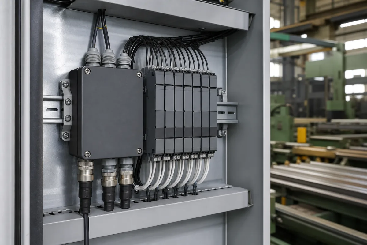
The illustrated cabinet takes encoder and sensor cables in through a connector box and lands them on a row of narrow DIN-rail interface modules before anything reaches the controller. On a line that cuts moving tube or bar to length, the measuring-wheel or motor encoder signal has to reach more than one device at a level each of them accepts. An encoder maker's bulletin on output types and two Kübler signal-splitter datasheets set out what that interface does.
Covers the signal interface between incremental or SinCos encoders (including measuring wheels) and the controllers, drives and counters that read them: output level (HTL, TTL/RS422, open collector), differential wiring, signal splitting, level conversion and SinCos-to-pulse conversion in DIN-rail modules. The original catalogue definition, a general I/O and fieldbus interface between a control system and a flying shear or saw, belongs on the Industrial control systems page; machine control cabinets are on 630, machine control units on 960, flying saw synchronisation on 2839, CNC encoder feedback (1 Vpp, EnDat) on 1146, and measuring-wheel length counters on 1365.
CNFX editorial research · Sources checked October 13, 2026 · 3 sources
Encoder Products Company's technical bulletin TB-109 opens with the rule that the receiving device determines the correct configuration of the encoder's outputs, and that no output type is better than another in itself.
EPC attributes the line driver's noise immunity to rejection of noise that arrives equally on a signal and its complement, and names the HV output as the option for long interconnecting cables that can degrade the signal.
The same bulletin warns that the paired lines must stay electrically balanced; if they do not, ringing and spurious oscillations appear on the lines and at higher frequencies can cause false counting in the load device. On a cut-to-length line a false count is a length error on the cut piece (editorial reading).
Output type (EPC TB-109)
What it does
What to watch
Open collector (OC)
Current-sinking output; lets the encoder run at one voltage with the output pulled up to another, for example 5 V supply and a 24 V output level
Pull-up must be provided at the receiver
Pull-up (PU)
Open collector with an internal pull-up resistor to the encoder supply; EPC names values between 1,500 and 2,200 Ω
Sourcing current limited by supply voltage and the resistor
Push-pull (PP)
Sources current in the high state, sinks it in the low state
EPC: noise on the DC supply is passed straight into the counter or PLC input when the output is high
Differential line driver (HV)
Complementary signal pairs; meets RS-422 when operated at 5 V DC
Needs a differential receiver and one extra wire per channel
EPC also offers an H5 variant whose outputs are limited to a 5 V complementary line driver regardless of the encoder's supply voltage, which suits a 5 V differential receiver on a 24 V machine.
02
Splitting one pulse train to two devices: Kübler SP 2D-2D
Where a measuring wheel or motor encoder has to feed both the drive that synchronises the saw and a separate length counter or PLC, wiring the encoder in parallel to two inputs of different level does not solve it (editorial note). Kübler's SP 2D-2D is a DIN-rail module built for that job.
Kübler gives a lower input limit for asymmetrical (single-ended) signals, 250 kHz, than for symmetrical (differential) ones, 1 MHz, so the input format sets the top line speed the module can follow.
The control inputs let a PLC switch which input is passed to the outputs without contact bounce, for example changing over between two encoders (editorial reading of Kübler's description).
Because the module has no potential isolation, an earth-potential difference between the encoder side and a remote controller passes through it; that has to be solved with grounding and shielding or with an isolated module.
Item
Kübler SP 2D-2D (datasheet page)
Function
Universal encoder interface for level conversion, distribution and contactless, bounce-free switching of encoder signals
Inputs
2 pulse inputs: A, B, 0 (HTL) or A, /A, B, /B, 0, /0 (RS422)
Input frequency
Up to 250 kHz asymmetrical, up to 1 MHz symmetrical
Outputs
2 channels, HTL or RS422, separately adjustable per output
Control inputs
2, for HTL/PNP signals at 10 to 30 V DC
Conversion
TTL to HTL and the reverse
Isolation
None (stated as without potential isolation)
Supply, housing
12 to 30 V DC; 22 × 102 × 102 mm; −20 to 60 °C; IP20; screw terminals
03
SinCos in, SinCos and square wave out: Kübler SP 1SC-2SC2D
A servo motor on the saw carriage may report position as 1 Vpp sine and cosine, while the length counter next to it only reads square-wave pulses. Kübler's SP 1SC-2SC2D splits the SinCos signal and converts it at the same time.
Kübler describes the duplication as lossless: both SinCos outputs carry the input signal in its original format, so the servo drive keeps its full analogue resolution while the counter gets pulses.
The 0 to 45 °C rating is narrower than the SP 2D-2D's −20 to 60 °C, which matters in an unheated mill bay or a cabinet next to a hot saw (editorial comparison of the two datasheets).
Item
Kübler SP 1SC-2SC2D (datasheet page)
Input
1 Vpp: SIN+, SIN−, COS+, COS−, REF+, REF−
SinCos outputs
2, same format as the input
Incremental outputs
2, A, /A, B, /B, 0, /0, adjustable for TTL/RS422 or HTL (10 to 30 V DC)
Maximum SinCos input frequency
500 kHz
Encoder supply
5 V or 24 V, switchable
Supply, housing
17 to 30 V DC; 22 × 102 × 102 mm; 0 to 45 °C; IP20; screw terminals and Sub-D
Both modules are listed as IP20 and belong inside a closed cabinet like the one illustrated.
04
What to tell an interface supplier
Paste it into your enquiry below or into an email to a maker, then replace every bracket.
Give the encoder or measuring-wheel type and output (HTL, TTL/RS422, open collector or 1 Vpp SinCos), encoder supply voltage, pulses per revolution and maximum line speed, so the pulse frequency can be checked, every device that needs the signal and the input level each one accepts, cable length between encoder and cabinet, and ambient temperature in the cabinet. Ask for the input frequency limit per signal type, output level options per channel, whether the module isolates input from output, and how switching between encoders is controlled.
Explore company information and manufacturing capabilities, then discuss the scope of your project with a relevant supplier.
Share this page
Compiled and source-reviewed by the CNFX editorial team.
Each manufacturer above links to the page on that company's own website where the product is listed, with the date we checked it. How we source and review
· Page last updated 13 October 2026
Buyer questions
Should an encoder for a cutting line have HTL or RS422 outputs?
EPC's TB-109 says the receiving device determines the output configuration; if the controller takes differential signals, a differential line driver gives noise immunity and suits long cables. [1]
Can one encoder feed two controllers with different input levels?
Yes, through a splitter such as Kübler's SP 2D-2D, which takes HTL or RS422 inputs and sets each of its two outputs to HTL or RS422 separately. [2]
How fast can a signal splitter run?
Kübler states up to 250 kHz for asymmetrical and up to 1 MHz for symmetrical inputs on the SP 2D-2D, and 500 kHz maximum SinCos input on the SP 1SC-2SC2D. [2][3]
Sources and what still needs a direct check
Sources checked 2026-10-13. An encoder maker's technical bulletin on output types, and Kübler datasheet pages for an incremental signal splitter and a SinCos splitter-converter.