Editorial Technical Reference

Lance Carriage/Positioning Mechanism

This page explains how Lance Carriage/Positioning Mechanism is classified within Basic Metal Manufacturing. Technical values and manufacturer relationships are research references; confirm the current specification and supplier evidence for each order.

Technical Definition & Core Assembly

Mechanism for precise positioning and movement of oxygen lances in metallurgical processes
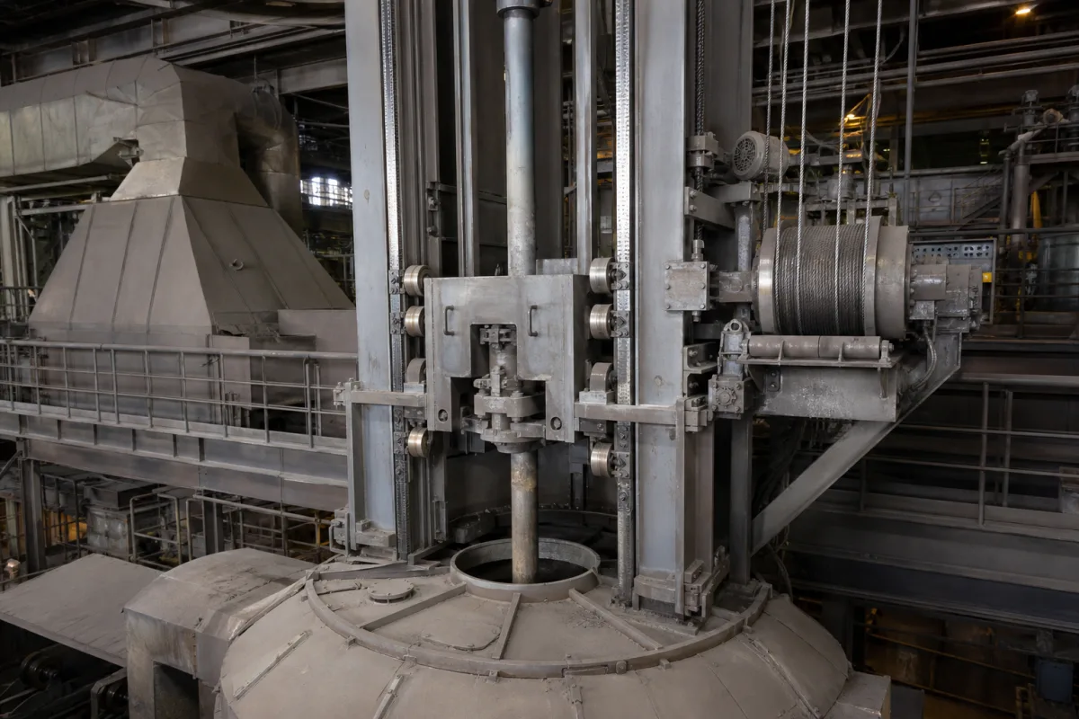
Representative product image. Confirm appearance and specifications with the manufacturer.

Product Specifications

Technical details and manufacturing context for Lance Carriage/Positioning Mechanism

Definition
The Lance Carriage/Positioning Mechanism is a component used in basic metal manufacturing, specifically for steelmaking furnaces or converters. It enables controlled horizontal and vertical movement of oxygen lances, ensuring accurate positioning for optimal oxygen injection during refining operations. The mechanism typically consists of a motor-driven carriage that travels on rails or tracks, combined with hydraulic or pneumatic positioning systems. Feedback control systems maintain precise positioning during operation, allowing the lance to be moved to specific coordinates as required by the process.

This mechanism is designed to handle rated lifting capacities from 5 to 20 tonnes, with stroke lengths ranging from 3000 to 8000 mm. Positioning accuracy is maintained within ±5 mm to ensure lance tip alignment with the tuyere. Traverse speeds vary from 0.1 to 0.5 m/s, and drive power ranges from 5.5 to 22 kW. The system operates on a three-phase industrial supply of 380–690 V AC, conforming to IEC 60038. It is designed for operating temperatures from -20°C to 60°C, with ingress protection ratings of IP54 to IP65 per IEC 60529. Structural steel grades Q235B to Q345B (per GB/T 1591) are used for the frame and rails. Rail gauge ranges from 1500 to 3000 mm, and carriage weight is between 1500 and 5000 kg.

Selection of a specific mechanism depends on furnace bay layout, lance weight, required stroke, and environmental conditions. Interfaces include the lance assembly, furnace structure, and control system. Verification questions should address actual load requirements, stroke limits, and compatibility with existing rails and power supply. Maintenance signals include unusual vibrations, positioning drift, or wear on guide rails. Failure boundaries are defined by load limits, stroke limits, and environmental ratings. Always verify model-specific values and standards with the legal manufacturer or supplier.
Working Principle
The mechanism uses a motor-driven carriage that moves along rails or tracks. The carriage supports the lance assembly and is driven by an electric motor, with hydraulic or pneumatic actuators providing additional positioning control. Feedback control systems, such as encoders or limit switches, monitor the carriage position and adjust the drive to achieve the desired coordinates. This allows precise horizontal and vertical movement of the lance, ensuring accurate placement for oxygen injection. The system is designed to operate within specified speed and accuracy ranges, with safety interlocks to prevent over-travel or collisions.
Common Materials
Structural steel, Alloy steel components, Wear-resistant guide rails
Technical Parameters
ParameterTypical rangeNotes & selection driver
Rated Lifting Capacity5–20 tDetermines lance weight and carriage strength
Stroke Length3000–8000 mmMust cover furnace opening and retract position
Positioning Accuracy±5 mmEnsures lance tip alignment with tuyere
Traverse Speed0.1–0.5 m/sAffects cycle time and control stability
Drive Power5.5–22 kWSized for acceleration and friction
Supply Voltage380–690 V ACThree-phase industrial supplyIEC 60038
Operating Temperature-20–60 °CAmbient around furnace; higher near lance
Ingress ProtectionIP54–IP65Protects against dust and water splashesIEC 60529
Material GradeQ235B–Q345BStructural steel for frame and railsGB/T 1591
Rail Gauge1500–3000 mmMatches furnace bay layout
Carriage Weight1500–5000 kgInfluences foundation and rail design

Ranges are indicative industry figures for RFQ preparation, not a supplier commitment. Confirm every value and standard with the legal manufacturer before ordering.

Components / BOM
  • Carriage Frame Part
    Structural support for lance assembly and movement components
    Material: Structural steel
  • Drive Mechanism
    Provides motive power for carriage movement along tracks
    Material: Alloy steel gears and bearings
  • Positioning Actuator
    Fine adjustment of lance vertical and horizontal position
    Material: Hydraulic cylinders or electric actuators
  • Guide Rails/Tracks Part
    Provides precise guidance for carriage movement
    Material: Wear-resistant steel rails
  • Control System Interface
    Receives positioning commands and provides feedback
    Material: Electronic components and sensors
  • Encoder or Limit Switch
    Reports where the carriage actually is, which is what the drive corrects against.
  • Safety Interlock
    Stops travel before the carriage runs past its limits or into something.

Industry Taxonomies & Aliases

Commonly used trade names and technical identifiers for Lance Carriage/Positioning Mechanism.

Applied To / Applications

This component is essential for the following industrial systems and equipment:

Industrial Ecosystem & Supply Chain Structure

Complementary Systems
Downstream Applications
Specialized Tooling

Application Fit & Sizing Matrix

Operational Limits
pressure: Max 10 bar (hydraulic/pneumatic system pressure)
other spec: Positioning accuracy: ±1 mm, Max lance travel: 5-15 m (configurable), Max load capacity: 500-2000 kg (depending on configuration)
temperature: Ambient to 150°C (operating), up to 250°C (intermittent exposure)
Media Compatibility
✓ Oxygen gas (industrial grade) ✓ Molten steel/slag environments (with appropriate cooling/lance protection) ✓ Water-cooled lance systems
Unsuitable: Highly corrosive acidic environments (e.g., hydrochloric acid pickling lines) due to potential material degradation
Sizing Data Required
  • Required lance travel distance (m)
  • Maximum lance load including cooling systems (kg)
  • Required positioning speed and acceleration/deceleration rates (m/s, m/s²)

Reliability & Engineering Risk Analysis

Failure Mode & Root Cause
Wear and misalignment of linear guide rails
Cause: Inadequate lubrication, contamination ingress, or improper installation leading to uneven load distribution and accelerated wear
Motor or drive system failure
Cause: Overloading, electrical issues (e.g., voltage spikes, overheating), or mechanical binding causing excessive torque demand and component degradation
Maintenance Indicators
  • Unusual grinding or scraping noises during carriage movement
  • Visible misalignment or wobble in the carriage positioning
Engineering Tips
  • Implement a proactive lubrication schedule with high-quality, compatible lubricants and ensure seals are intact to prevent contamination
  • Regularly calibrate and verify alignment using precision tools, and install condition monitoring sensors (e.g., vibration, temperature) for early fault detection

Indicative industry ranges for design and RFQ preparation. Confirm the exact figures and applicable standard with the manufacturer before specifying.

Compliance & Manufacturing Standards

Applicable Standards
ISO 286-2:2010 (Geometrical product specifications - Limits and fits) ANSI/ASME B5.54-2005 (Methods for Performance Evaluation of Computer Numerically Controlled Machining Centers)

Quoted from the published standard.

Manufacturing Precision
  • Linear positioning accuracy: +/-0.01 mm over full travel
  • Parallelism of guide rails: 0.02 mm per meter
Quality Inspection
  • Laser interferometer positioning accuracy test
  • Hardness testing of bearing surfaces (Rockwell C scale)

Manufacturers of Lance Carriage/Positioning Mechanism

Manufacturer profiles associated with Lance Carriage/Positioning Mechanism.

Sourcing Lance Carriage/Positioning Mechanism from China?
Tell us your specification and target quantity — we will match it against manufacturer records and come back with the factories that fit.
Request manufacturers We manufacture this

Manufacturer listings support early research and capability understanding. They are not certification, ranking, or transaction guarantees.

Technical documentation
Request current drawings, revision history, and a signed specification sheet.
Manufacturing capability
Verify equipment lists, process limits, capacity, and representative production evidence.
Inspection readiness
Confirm test methods, calibrated equipment, sampling plans, and traceable reports.
Supplier transparency
Check the legal entity, factory address, ownership, certifications, and direct contacts.

CNFX does not score or rank suppliers. Buyers must verify all claims and documents with the legal manufacturer before ordering.

Supply Chain Compatible Machinery & Devices

Electroslag Remelting Furnace

An industrial furnace used in basic metal manufacturing for secondary refining of alloys through the electroslag remelting (ESR) process.

Explore Specs →
Molten Metal Temperature Measurement System

Automated system for continuous temperature monitoring of molten metals during processing.

Explore Specs →
Molten Metal Degassing System

The Molten Metal Degassing System is an industrial system used in basic metal manufacturing to remove dissolved hydrogen, oxygen, and nitrogen from molten aluminum, steel, and other non-ferrous metals.

Explore Specs →
Molten Metal Level Control System

Automated system for precise molten metal level monitoring and control in furnaces and vessels.

Explore Specs →

Frequently Asked Questions

What is the typical stroke length of this mechanism?

The stroke length ranges from 3000 to 8000 mm, depending on the model and application. It must cover the furnace opening and retract position. Verify the exact stroke for your specific model with the manufacturer.

What is the positioning accuracy?

The positioning accuracy is ±5 mm, ensuring lance tip alignment with the tuyere. This is a reference value; confirm the actual accuracy for your model.

What are the electrical supply requirements?

The mechanism operates on a three-phase industrial supply of 380–690 V AC, per IEC 60038. Ensure your facility's power supply matches the model's requirements.

What environmental conditions can it withstand?

It is designed for operating temperatures from -20°C to 60°C and has ingress protection ratings of IP54 to IP65 per IEC 60529. Confirm these ratings for your specific model.

Data Basis

Editorial classification, named public sources where available, and source-reviewed manufacturer records.

Preliminary Technical Classification
This page supports structured research, RFQ preparation, and supplier evaluation. It does not replace buyer-led supplier qualification, standards review, or technical approval.
Buyer enquiry

Request manufacturing insight for Lance Carriage/Positioning Mechanism

Ask for use case, specification boundaries, supplier type, and RFQ preparation information for this product.

Where it goes
Straight to the CNFX editorial desk, and to the manufacturer if this product is linked to a claimed profile. Nothing is broadcast to a supplier list.
Your details stay here
We do not sell or rent enquiry data, and we do not add you to a mailing list. Used only to answer this request.
No commission, no middleman
CNFX is a directory. We take no cut of any order and never negotiate on a supplier's behalf.
What we don't claim
A listing is not an endorsement. Qualify every supplier and verify every figure yourself before ordering.

Your business information is used only to process this request.

Thank you! Your message has been sent. We'll respond within 1–3 business days.
Sorry, we couldn't send your message. Please try again, or email us at contact@cnfx.com.

Need to Manufacture Lance Carriage/Positioning Mechanism?

Compare manufacturer profiles with relevant product and process capability.

Previous Product
Work Rolls
Last Product
Get QuotesChat