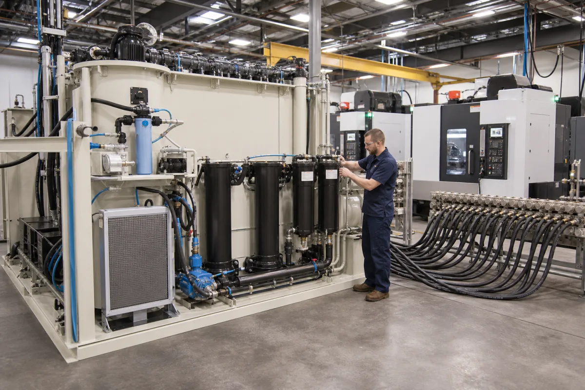
Central coolant management system for a machine-tool hall: one filter plant and supply header feeding a row of CNC machines, sized in litres per minute and checked as one fluid
One coolant loop for a whole row of machine tools · pump-back stations, central filter capacity in l/min, supply stations at each machine, and the TRGS 611 checks on the shared fluid
A machine-side coolant tank serves one machine. A central coolant management system serves a hall: the chip-laden fluid from every machine is pumped back to one plant, cleaned there, cooled, and sent out again through a supply header to all of them. The questions change with that. The filter has to be sized for the sum of the flows, each machine needs a steady supply pressure even when its neighbours start and stop, and because all the machines now share one batch of fluid, its concentration and condition have to be measured and corrected in one place.
Central coolant (cooling lubricant) systems that serve a group of machine tools from one plant: pump-back stations and return pipework, central filter plants, clean tanks with coolers, supply pumps and headers, supply stations at the machines, and the monitoring of the shared water-mixed fluid. Machine-side tanks and filter units for a single machine are covered on the Coolant system for CNC machine tools page; through-spindle high-pressure units on the High-pressure coolant systems page; portable sump-cleaning carts on the Filter unit for machine tool coolant page; tramp oil skimmers on their own page; chip conveyors on the Chip conveyor for CNC machine tools page; and glycol pumps for closed chiller loops on the Glycol coolant pump page.
CNFX editorial research · Sources checked October 13, 2026 · 6 sources
Pump-back stations, central filter and supply header for a machine train of 30 or more
KNOLL describes its circuit system as the fully automatic return of the chip and coolant mixture from the machines on the loop to a central separator or filter, which then supplies the machines with cleaned coolant, and places it in large production areas with a machine train of 30 or more machines or as an island solution for wet machining. [1]
The main components KNOLL lists run in loop order: optional chip conveyor and chip reducer at each machine, pump-back stations, return pipework, an optional chip pre-separator, dirty and/or clean tank, the coolant filter plant, supply pumps, flow pipework, optional pressure-increasing stations (central or at the machines), control technology and optional downstream chip processing. It notes that the pipelines run above the floor, so no plant components sit in the hall floor. [1] One of its reference plants separates chips in two stages, 100 µm and then 30 µm, and sends the chips by distribution conveyors to two truck containers. [1]
At the machine end, HOFFMANN's supply station is the interface between the central system and one machine tool: it has a clean and a soiled section, level monitoring in the clean section, one or more machine feed pumps, and its own control independent of the central system. HOFFMANN says it buffers short interruptions of the central supply and pressure shocks in the system and delivers coolant at constant pressure. [5] Options it lists include frequency-controlled return and supply pumps and a tropical version for ambient temperatures up to +50 °C. [5]
List every machine on the loop with its coolant flow, supply pressure and chip type, and mark which ones need a local supply or pressure-boosting station.
02
Central filter capacity from 90 l/min cyclone modules to 5,600 l/min vacuum band filters
KNOLL says the choice of central filter depends on the number of machines, the type of machining, the chip material and the coolant quality required. [1] Its central-systems brochure gives the capacity of each filter type per unit, which is the figure to compare against the sum of the machine flows. [2]
Editorial calculation, with assumed figures: 30 machines drawing 40 l/min of flood coolant each need 30 × 40 = 1,200 l/min of filtered fluid, inside the 1,500 l/min of one KNOLL VL unit or the 2,200 l/min top of HOFFMANN's UBF range, but nearly five TURBO units at 250 l/min each. The per-machine flow here is an assumption; use the measured or catalogue flow of each machine on the loop.
HOFFMANN fits a cooler in the clean tank of its precoat filters to bring the coolant to the temperature the machines need, and can add separate circuits for spindle or motor cooling. [4] It explains that a constant coolant temperature keeps tool and workpiece at constant temperature for tight tolerances, and that in water-based emulsions cooling also slows the growth of germs. [4]
Size the central filter for the total flow of all machines running together, and state the filter fineness each process needs; grinding of hard metal is quoted at 1–3 µm, far finer than a general machining loop.
03
Nitrite at 20 mg/l, pH within 0.5 points, 3–5% or 6–12% concentration: checking the shared fluid
In a central system every machine runs on the same fluid, so the checks German rules require for water-mixed cooling lubricants are made on one batch. helcotec's practice sheet summarises TRGS 611: nitrite in the coolant weekly with a limit of 20 mg/l, or 80 mg/l for inhibited fluids citing DGUV 109-003; the interval may be extended to four weeks after three consecutive readings below 10 mg/l, though helcotec recommends staying weekly. [6]
helcotec links low concentration to an empty concentrate drum or too weak a top-up mix, with corrosion and germ growth as consequences, and high concentration to a low fill level or too strong a mix, with reduced cooling and skin irritation; its remedies are to raise or lower the top-up concentration, or exchange part of the batch. [6] Editorial note: on a central loop the top-up goes into one tank, so a dosing or mixing unit there (KNOLL lists coolant metering and mixing devices among its central-system accessories [1]) replaces separate top-ups at each machine.
Check
Interval
Limit or range
Nitrite in the coolant
Weekly; 4 weeks after 3 readings below 10 mg/l [6]
Paste it into your enquiry below or into an email to a maker, then replace every bracket.
Machines: [number and type; coolant flow and supply pressure for each]
Chips: [material; short or long; quantity per hour]
Fluid: [emulsion or solution; concentration; oil]
Return: [pump-back stations at machines; pipe route above floor]
Filter: [type; total capacity l/min; fineness µm; consumables or none]
Clean tank and cooling: [volume; supply temperature; cooler capacity]
Supply: [header pressure; local supply or pressure-boosting stations]
Care: [dosing and mixing unit; skimmer; monitoring of nitrite, pH, concentration]
Chips out: [conveyors; containers; chip processing]
Explore company information and manufacturing capabilities, then discuss the scope of your project with a relevant supplier.
Share this page
Compiled and source-reviewed by the CNFX editorial team.
Each manufacturer above links to the page on that company's own website where the product is listed, with the date we checked it. How we source and review
· Page last updated 13 October 2026
Buyer questions
How many machines does a central coolant system serve?
KNOLL places its circuit system in production areas with a machine train of 30 or more machines, or as an island solution. [1]
What filter capacity is available for a central system?
KNOLL's units range from 90 l/min per cyclone module to 5,600 l/min for the VLX vacuum filter; HOFFMANN's UBF covers 200–2,200 l/min and its precoat filters 10–10,000 l/min. [2][3][4]
What does a supply station at the machine do?
HOFFMANN describes it as the interface between the central system and one machine: it buffers interruptions and pressure shocks and supplies coolant at constant pressure. [5]
How often must nitrite be checked?
helcotec's summary of TRGS 611 gives weekly checks with a 20 mg/l limit, extendable to four weeks after three readings below 10 mg/l. [6]
What coolant concentration is targeted?
helcotec gives 3–5% for solutions and 6–12% for emulsions, measured twice a week by refractometer. [6]
Sources and what still needs a direct check
Sources checked 2026-10-13. KNOLL Maschinenbau's central-systems page and brochure, HOFFMANN's pages on its vacuum belt filter, precoat filter and supply station, and helcotec's cooling lubricant practice sheet summarising TRGS 611.