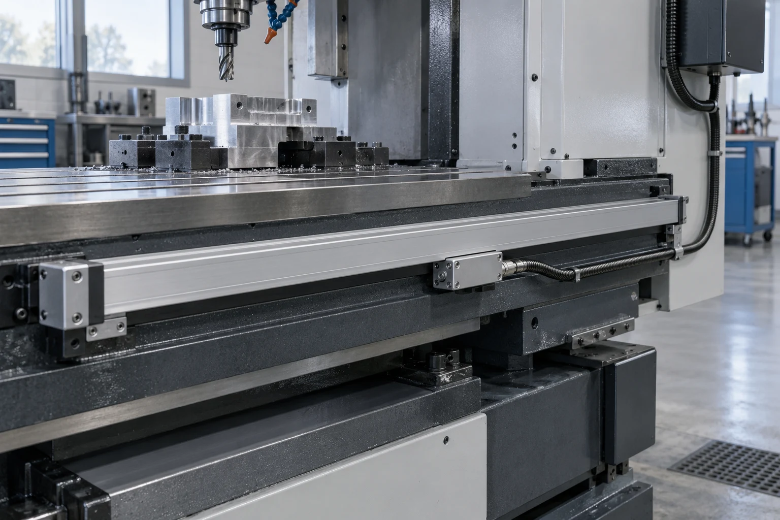
A sealed glass linear encoder reads travel at the machine slide. Its grating, scanning carriage and signal electronics form the measuring chain; its mounting and temperature determine how that measurement relates to the workpiece. Compare the BIGA ASD4 options with HEIDENHAIN’s LS 487/477 data, then specify the measuring length, interface and installation conditions together.
CNFX editorial research · Sources checked October 9, 2026 · 10 sources
Follow the glass scale through scanning and signal evaluation
For an incremental optical scale, relative movement changes the light reaching the scanning sensors; the electronics turn that changing pattern into position increments. A reference mark establishes the reference after it is crossed. HEIDENHAIN describes imaging scanning for its LS family; BIGA states a glass grating and ball-bearing-guided reading head, but does not publish ASD4’s internal optical or electronics design [1][3].
Functional part / BOM reference
What it does
Materials and configuration boundary
Graduated scale
The periodic grating is the measuring standard; a reference track supports referencing [1].
ASD4 is described as glass. LS 4x7 uses a glass scale with DIADUR grating; do not substitute a steel or magnetic scale as the same configuration [3][1].
Scanning carriage / reading head
Optical scanning converts changes in the projected grating into electrical signals; the guided carriage maintains the measuring relationship [1].
BIGA states ball-bearing guidance, but head alloy, sensor and optical part numbers are not published [3].
Mounting block and fastening arrangement
Connects the guided scanning carriage to the machine; the scale housing mounts relative to the other machine element [1].
Use the specific mating dimensions, gap and mounting option. The bracket alloy and ordered fastener list are not established for ASD4.
Signal interpolation / evaluation
Subdivides a signal period into measuring steps. LS 477 has integrated interpolation and requires downstream four-fold evaluation for its listed steps; LS 487’s step depends on the receiving interpolation [1].
This is a function, not a separately confirmed ASD4 spare component. Order the signal and compatible receiving electronics together.
Housing and sealing lips
The enclosure protects the measuring components; elastic lips seal the moving connection [2].
HEIDENHAIN states an aluminium housing. Lip material and ASD4 housing alloy are not identified by the reviewed sources.
Cable and electrical connection
Carries power and signals to the receiving electronics; flexing and routing impose installation limits [1].
LS 4x7 uses a separate adapter cable. Pin assignments, cable length and flex rating must match the purchased configuration; conductor or jacket materials are not supplied here.
This is a functional structure for sealed optical encoders, not a complete manufacturing BOM or interchangeable spare-parts list. HEIDENHAIN’s p.5 LC 115 diagram supports the general guided/sealed design, not the identity of ASD4’s internal parts.
02
What an accuracy grade actually promises
Closing the position loop on the slide lets the control correct thermal growth of the ball screw, reversal error and screw pitch error [1]. How much of that you gain depends on what the scale's accuracy figure covers.
The grade limits baseline error over a stated section
HEIDENHAIN defines the grade as the upper limit of baseline error within any section up to one metre. It is not a rate that can simply be multiplied by the full axis length, nor a promise for the complete installed machine. Its final inspection document gives the measured baseline error; the LS series also records the position-error curve over the entire measuring length [1].
Read the 20 °C calibration condition separately from the operating range
HEIDENHAIN’s calibration chart is valid at its 20 °C reference temperature; the operating-temperature range instead states when the encoder functions properly. BIGA publishes its ASD4 accuracy options at 20 °C over 1000 mm, but does not establish the same section-by-section definition or inspection document on the page reviewed [1][3].
Interpolation error matters for surface finish
Interpolation error acts within each signal period, even at very low speed, and shows up in surface quality; it is stated separately as a maximum value [1]. Ask for it if the scale feeds a CNC rather than a readout.
Mounting tolerances and coefficient of thermal expansion
03
Compare two published spec sheets line by line
BIGA’s page lists ASD4 glass-scale options; HEIDENHAIN’s September 2025 catalogue separates the LS 487 analogue model from the LS 477 TTL model. Compare the fields below, but obtain one order-code-specific configuration rather than treating every listed option as interchangeable.
The catalogue’s LS 477 measuring steps require four-fold evaluation by the downstream electronics. Resolution is not a replacement for graduation accuracy, interpolation error or installation error; the BIGA page does not map each signal option to every stated length and resolution [1][3].
04
Specify the measurement and installation conditions with each parameter
A travel range, an electrical signal and an accuracy grade answer different questions. The following fields use the published model examples; they do not give a universal range for every linear encoder.
Parameter
Unit / field
Meaning and supported example
Measuring length
mm
Usable measured travel, not overall housing length. ASD4 lists 50–1000 mm; LS 4x7 lists discrete lengths 70–2040 mm and requires a spar from 1340 mm [3][1].
Resolution / measuring step
µm
Smallest evaluated increment. ASD4 options 0.5/1/5/10 µm; LS 477 1/0.5/0.25 µm after downstream four-fold evaluation. These are not accuracy grades [3][1].
Accuracy grade
µm; stated length and temperature
HEIDENHAIN’s baseline-error grade and final inspection chart are defined separately. BIGA’s ±3/±5/±8/±10 µm options are stated at 20 °C/1000 mm; request its test method and chart [1][3].
Repeatability
µm; test procedure
Repeated positioning must be distinguished from graduation accuracy and interpolation. A numerical ASD4 repeatability value is not established by the reviewed page; request the procedure and result.
Maximum traverse speed
m/min
Check the exact signal/interpolation combination. ASD4 lists 30/60 m/min; LS 477 lists 120, 60 or 30 m/min depending on interpolation and scanning frequency, so do not order from its family’s highest speed alone [3][1].
Output signal
Interface, connector, pinout
ASD4 lists TTL, HTL, EIA-422-A, 1 Vpp and 11 µApp. LS 487 is 1 Vpp and LS 477 TTL; these names do not establish direct controller compatibility [3][1].
Supply voltage
VDC; current, load condition
LS 487/477 list 5 V ±0.25 V without load and current below 120/140 mA respectively. The ASD4 page does not state the supply for every output option [1][3].
Operating temperature
°C
ASD4 lists 0–45 °C; LS 4x7 0–50 °C. These are operating ranges, not statements that the calibration error is unchanged throughout them [3][1].
Protection rating
IP; installation and purge arrangement
LS 4x7: IP53 under specified mounting conditions; IP64 with DA 400 purge air. The ASD4 page does not state its IP rating; sealed construction alone is not a rating [1][3].
Thermal expansion coefficient
K⁻¹; mounting configuration
LS 4x7 approximately 8 × 10⁻⁶ K⁻¹ for the stated mounting types, or 9 × 10⁻⁶ K⁻¹ with spar. ASD4’s coefficient is not published here [1][3].
Reference marks
Single/selectable/distance-coded
LS distance-coded referencing requires crossing two successive marks with compatible electronics; its 20 mm maximum traverse is model-family-specific. BIGA lists options without a matching decoding procedure [1][3].
Mass
kg; measuring length
LS 4x7 lists 0.4 kg + 0.5 kg/m of measuring length. This is the named series’ catalogue expression; ASD4 mass and the ordered system’s complete accessories need confirmation [1].
05
Allow for temperature before you blame the scale
The thermal behaviour of a linear encoder should match that of the workpiece, and it must expand and contract in a defined, reproducible way [1].
A 3 °C rise gives about 24 µm of dimensional change in this example
Using the LS 4x7 value α ≈ 8 × 10⁻⁶ K⁻¹ for the stated mounting types, ΔL = α × L × ΔT. For 1000 mm and +3 °C, the calculated change is about +0.024 mm (24 µm). With the mounting spar the catalogue gives approximately 9 × 10⁻⁶ K⁻¹, giving about 27 µm under the same assumptions. These are dimensional-change estimates, not measured axis-position errors: the installation, temperature distribution, workpiece expansion and any compensation determine the final relationship [1].
Ask for the coefficient if it is missing
The ASD4 specification reviewed lists accuracy, resolution and temperature ranges but no coefficient of thermal expansion [3]. Without it you cannot predict how the scale tracks a steel or cast-iron machine bed.
Record shop temperature
Note the range at the machine over a working day.
Get the scale coefficient
From the datasheet or supplier in writing.
Check how it is fixed
Fixed at its midpoint with flexible fastening elements, or rigidly to the surface; this changes how it follows the machine [1].
Decide on compensation
Discuss compensation against the workpiece and machine’s actual thermal behaviour; check it through the applicable machine acceptance procedure. The dimensional estimate alone is not an axis-accuracy test.
06
Mount it so it stays accurate
The mounting points below come from the HEIDENHAIN catalogue; HEIDENHAIN states that its mounting instructions, not the brochure, are binding [1]. Ask your supplier for the equivalent instructions for the scale you buy.
Mount the scale as close as possible to the working plane to keep Abbe error low [1].
Use solid machine elements; avoid hollow parts and small intermediate brackets that vibrate [1].
Keep the scale away from heat sources such as motors and hydraulic units [1].
Point the sealing lips downward or away from splash water [1].
Set the gap between scale unit and scanning unit with the shipping brace or a mounting gauge, and check it with test gauges; on the slimline series the nominal gap is 1.0 mm with test limits of 0.7 and 1.3 mm [1].
Connect both scanning unit and scale housing to functional earth with low resistance, below 1 Ω [1].
Respect the cable's minimum bend radius, especially on flexing runs [1].
Never use a hammer to adjust or position the encoder [1].
07
Protect the scale in a machine with coolant
Sealed scales are enclosed in an aluminium housing with elastic sealing lips [2], but sealing alone has limits.
As installed
IP53 or IP54 per IEC 60529 when mounted with the sealing lips facing away from splash water [1].
With purge air
HEIDENHAIN specifies IP64 with the stated purge arrangement; its flow-regulated connectors provide 7 litres/min per encoder at approximately 1 bar inlet pressure. This is not permission to connect an arbitrary unregulated shop-air line [1].
Air quality into the encoder
Air entering the encoder: ISO 8573-1:2010 class 1 solid contaminants, class 4 pressure dew point (maximum 3 °C) and class 1 total oil (maximum 0.01 mg/m³). The DA 400 filter’s inlet requirements are different; do not substitute them for encoder-inlet air quality [1].
Wear parts
HEIDENHAIN lists the sealing lips on sealed linear encoders among components "subject to wear depending on the application and how they are deployed" and adds: "This especially applies to cables that are subject to frequent flexing." Use the purchased model’s instructions for inspection or replacement; internal cleaning methods and solvents are not established here [1].
The BIGA page describes a sealed structure and a ball-bearing guided reading head but does not state an IP rating or purge-air option [3]; ask for both before using it on a wet grinder or machining centre.
08
Copy this RFQ and fill in the brackets
Paste it into your enquiry below or into an email to a maker, then replace every bracket.
Product: sealed optical linear encoder, model/order code [ ], quantity [ ]
Travel: measuring length [mm], available housing space [mm], axis [ ]
Accuracy: stated grade [ ], reference temperature [ ], section/length definition [ ]; calibration chart [ ]
Signal: [ ], measuring step [ ], receiving DRO/CNC model [ ], connector/pinout [ ]
Reference: mark arrangement [ ], compatible evaluation/homing method [ ]
Motion: maximum speed [m/min], cable flexing and drag-chain requirements [ ]
Mounting: drawing/mating dimensions [ ], spar [ ], gap/gauges [ ], fastening/earth instructions [ ]
Thermal: mounting configuration, expansion coefficient and compensation basis [ ]
Environment: coolant/mist/dust [ ], required IP with stated installation [ ], purge arrangement and air quality [ ]
Documents: model datasheet, mounting instructions, per-unit inspection chart, replacement lips/cable availability [ ]
Delivery: destination [ ], date [ ]
7 companies list this product among what they make. Company figures are quoted from each
company's own website; every card states where the relationship came from.
Dongguan City BiGa Grating Machinery Co., Ltd.
Dongguan, Guangdong (entity region; model plant to be verified), CN
ASD4 glass grating scales are listed with accuracy, resolution, output and speed options. The page gives 20 °C/1000 mm accuracy conditions but does not map every option to an order code or publish its expansion coefficient, IP rating and model-specific supply limits. Obtain one consistent configuration and installation drawing.
The absolute-linear category lists RDA100 and RLA100/RLA400/RLA-700/RLA-900. Its open and absolute models are not automatically substitutes for the sealed incremental glass scales compared above.
YS1000 is listed as a sealed optical encoder. Its selector offers 70–1020 mm travel and 0.05–1 µm steps, while the specification text states 30–360 mm and 1/5 µm; cable text also differs between 2 m and 3 m. These conflicting sections need a dated order-code-specific datasheet; CNFX does not choose one as the confirmed supply configuration.
The official category separates tape encoder, linear scale and DRO products. DS401 is a digital display/data-processing meter for two-dimensional measuring instruments, not the scale itself. Specify which scale and readout are required as separate parts.
The current site has a Linear scale & DRO category, but the page reviewed does not provide a specific scale model’s accuracy, interface or mounting specification. The category supports a product-range enquiry, not a verified model configuration or independent certification.
The official DLS-W page describes a linear encoder and lists TTL/EIA422A options. Its dimensions/pictures section is labelled DLS-M despite the DLS-W heading. Confirm a matching model drawing and signal/pinout before ordering.
The WTB(D) optical-scale page lists TTL/RS422 choices and distinguishes travel from housing length. It also labels 0.0005/0.001/0.005 mm as accuracy and repeats them as resolution, without accuracy test conditions. Request separate verified accuracy and step specifications; do not adopt those figures as a calibration grade.
Explore company information and manufacturing capabilities, then discuss the scope of your project with a relevant supplier.
Share this page
Compiled and source-reviewed by the CNFX editorial team.
Each manufacturer above links to the page on that company's own website where the product is listed, with the date we checked it. How we source and review
· Page last updated 13 October 2026
Buyer questions
Is a 1 µm resolution scale accurate to 1 µm?
No. A measuring step is an evaluated signal increment. HEIDENHAIN separately defines its baseline-error grade within sections up to one metre, and calibrates at 20 °C. BIGA’s own grade conditions must be read from its model documentation. [3][1]
Why does my scale read differently in summer?
The LS 4x7 example has an approximate expansion coefficient of 8 × 10⁻⁶ K⁻¹ for specified mounting types, or 9 × 10⁻⁶ K⁻¹ with a spar. A one-metre length therefore changes dimension by about 8 or 9 µm per °C. The installed reading also depends on mounting, the workpiece and compensation; dimensional change alone is not measured machine error. [1]
What does distance-coded reference mean?
On the HEIDENHAIN LS distance-coded versions, compatible downstream electronics establish the reference after crossing two successive coded marks, with a maximum traverse of 20 mm. BIGA lists a distance-coded option, but its reviewed page does not provide the matching decoding procedure; confirm that with the receiving control. [3][1]
Do I need purge air?
HEIDENHAIN specifies IP64 for its sealed encoders with the prescribed purge arrangement and encoder-inlet air quality. Its flow-regulated connection uses approximately 7 litres/min per encoder at 1 bar inlet pressure. This does not establish the same rating or air requirements for ASD4. [1]
Sources and what still needs a direct check
Sources checked 2026-10-09. The HEIDENHAIN September 2025 catalogue was read for the cited operating, optical, accuracy, mounting and LS 4x7 sections; the LS specification table and the general sealed-encoder drawing were visually checked. BIGA provides the ASD4 options, without an order-code mapping. Other company pages establish their stated product range and unresolved page conflicts, not independent certification. Sources checked 9 October 2026.
Specific model mounting/maintenance instructions are binding; the brochure and this functional structure do not establish an internal service procedure.
Supplier-page conflicts remain unresolved: YiiDRO selector/specification travel, step and cable values; Metalcnc DLS-W/DLS-M picture label; Pinrui accuracy/resolution terminology. Confirm a dated configuration and drawing directly.
Buyer enquiry
Request manufacturing insight
for Encoder / Linear Scale
Ask for use case, specification boundaries, supplier type, and RFQ preparation
information for this product.
Where it goes
Straight to the CNFX editorial desk, and to the manufacturer if this product is
linked to a claimed profile. Nothing is broadcast to a supplier list.
Your details stay here
We do not sell or rent enquiry data, and we do not add you to a mailing list.
Used only to answer this request.
No commission, no middleman
CNFX is a directory. We take no cut of any order and never negotiate on a
supplier's behalf.
What to include
Share your product specifications, quantity, destination and target delivery date.
Need to Manufacture Encoder / Linear Scale?
Compare manufacturer profiles with relevant product and process capability.