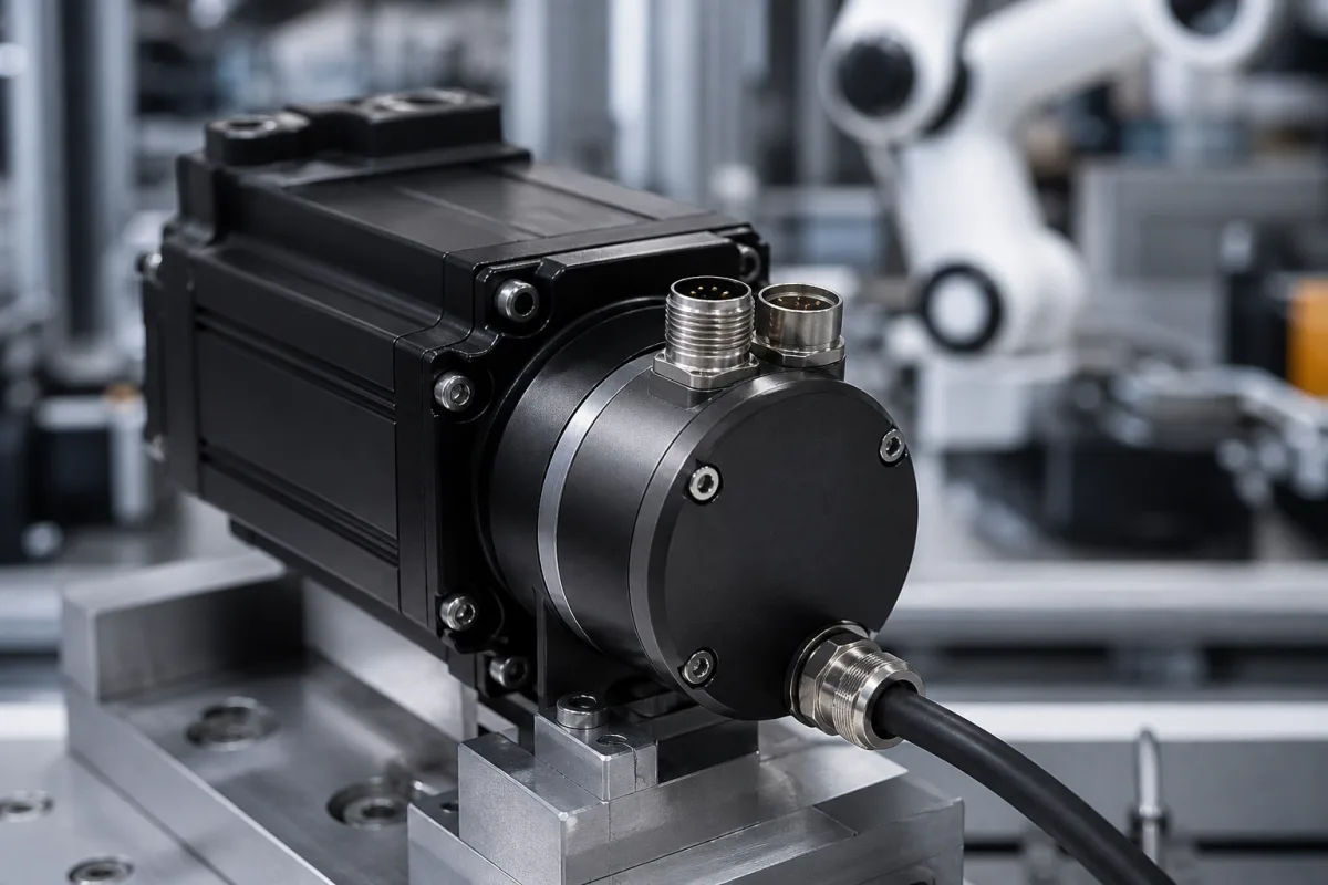
Servo motor feedback encoder: built-in absolute encoder with a digital drive interface (HIPERFACE DSL, BiSS)
Absolute encoders built into the back of a servo motor · bits per turn against real accuracy, the digital drive interface, and safety and temperature limits inside the motor
A servo motor's feedback encoder sits under the rear cover, on the motor shaft, and tells the drive the rotor angle for commutation and the shaft position and speed for the control loops. Built-in units are compact absolute encoders, singleturn or with a multiturn counter, that report over a digital serial interface rather than as pulse trains, and some carry a safety rating so the drive can use them for safe motion functions. This page compares three published units on resolution and accuracy, interface and supply, and the limits that apply inside a hot motor.
Absolute motor feedback encoders built into servo and BLDC motors: stator-coupled or hollow-shaft kit encoders and off-axis ring encoders with digital interfaces such as HIPERFACE DSL, BiSS and SSI, including safety-rated versions. Stand-alone shaft and hollow-shaft rotary encoders for machine axes, and the difference between resolution and accuracy, are covered on the High-resolution rotary encoder page; linear encoders and resolvers are outside this page.
CNFX editorial research · Sources checked October 12, 2026 · 3 sources
20 bit per turn is 1.24 arcsec, but the stated accuracy is ±35 to ±100 arcsec
SICK's EKM36-2KF0B0S03 gives 20 bit resolution per revolution, 4,096 absolutely countable revolutions, a system accuracy of ±100″ and signal noise (σ) of ±5″, by optical measurement. [1] Hengstler's AD36, an optical encoder with a geared multiturn for brushless servo motors, gives 12 to 19 bit singleturn over BiSS (12 to 17 bit over SSI), 12 bit multiturn, ±35″ absolute accuracy and ±7″ repeatability. [2]
Editorial calculation: 2^20 = 1,048,576 steps per turn, or 1,296,000″ / 1,048,576 ≈ 1.24″ per step; at 19 bit a step is about 2.47″. The AD36's ±35″ is about 14 of its 19 bit steps and the EKM36's ±100″ about 80 of its 20 bit steps, so the bit count says how finely the drive can resolve motion, not how close the reported angle is to the true one. A 12 bit multiturn counter, 2^12, equals the 4,096 revolutions SICK states.
The SICK data sheet also lists a measurement step of 262,144 per revolution, which is 2^18, alongside its 20 bit resolution; SICK's safety data give channel 1 as 18 bit or 20 bit. [1] Ask which figure applies to the delivered variant.
RLS's selection table lists a maximum of 17 bit for the smallest readhead and 20 bit for the larger ones, and RLS states that self-calibration removes the eccentricity error of the mounted ring. [3]
±0.05° (180″) before installation; typ. ±0.025° (90″) after self-calibration [3]
02
Drive interface and supply: HIPERFACE DSL on 4 pins at 7–12 V, or BiSS up to 10 MHz
The EKM36 talks HIPERFACE DSL through a 4-pin male connector, runs on 7 to 12 V with 8 V recommended, draws up to 150 mA, outputs the digital position value at 0 to 75 kHz and is ready within 500 ms of reaching its operating voltage. [1] It can also measure an external temperature resistance, NTC or PTC, over −40 to +160 °C. [1]
The AD36 sends fully digital position over BiSS with a variable clock up to 10 MHz, or over SSI together with 2,048 sine-cosine periods per turn at 1 Vpp and a 500 kHz bandwidth for older drives; it runs on 5 V −5 %/+10 % or 7 to 30 V, draws 50 mA singleturn or 100 mA multiturn without load, and reports its own temperature with 8 bit resolution along with warning and alarm bits. [2] The AksIM-2 offers BiSS, asynchronous serial, SPI, PWM or SSI on 4.5 to 5.5 V at 130 mA typical (150 mA maximum), with a 9 kHz bandwidth and up to 44 kHz refresh rate. [3]
Each encoder here lists its own interfaces and supply range; name the drive's encoder interface and supply voltage before choosing the encoder.
03
Inside the motor: up to 115–120 °C, 9,000–10,000 rpm, and SIL2 / PL d where the drive needs it
The EKM36-2 version is rated SIL2 (IEC 61508), SILCL2 (EN 62061), category 3 and PL d (EN ISO 13849) for safe increment, with a PFH of 4 × 10⁻⁸ at 90% diagnostic coverage that the drive must achieve, a mission time of 20 years and an MTTFD of 500 years. [1]
SICK states that the EKM36's EMC ratings apply only when the encoder is mounted in a conductive housing connected to the drive's central earth through the cable screen. [1] RLS rates the AksIM-2 from −40 to +105 °C and lists robot joints with a cable fed through the ring among its uses. [3]
1 company lists this product among what they make. Company figures are quoted from each
company's own website; every card states where the relationship came from.
Gertech (Weihai) Automation Technology Co., Ltd.
Manufacturing site to be confirmed for the order
Lists the GS-SV35 series servo motor encoder with a tapered shaft and A, B, Z, U, V, W outputs on RS422 line drivers, alongside single-turn BiSS and bus-based absolute encoders.
Explore company information and manufacturing capabilities, then discuss the scope of your project with a relevant supplier.
Share this page
Compiled and source-reviewed by the CNFX editorial team.
Each manufacturer above links to the page on that company's own website where the product is listed, with the date we checked it. How we source and review
· Page last updated 13 October 2026
Buyer questions
What does 20 bit resolution mean in arcseconds?
Editorial calculation: 1,048,576 steps per turn, about 1.24 arcsec per step; SICK still states ±100 arcsec system accuracy for its 20 bit EKM36. [1]
Can a motor feedback encoder be safety rated?
Yes. SICK rates the EKM36-2 version SIL2, SILCL2 and PL d, category 3, with a PFH of 4 × 10⁻⁸. [1]
How many turns does a multiturn motor encoder count?
The EKM36 and the AD36 count 4,096 revolutions (12 bit); the AksIM-2 option counts 0 to 65,535 (16 bit). [1][2][3]
How hot may a built-in encoder get?
SICK gives −20 to +115 °C for the EKM36 with the internal sensor at no more than 125 °C; Hengstler gives −15 to +120 °C for the AD36. [1][2]
Sources and what still needs a direct check
Sources checked 2026-10-12. Resolution, accuracy, interface, supply, safety and limits come from SICK's EKM36-2KF0B0S03 product data sheet, Hengstler's AD36 motor feedback data sheet and RLS's AksIM-2 data sheet MBD01_07. Values apply to the models named.