Editorial Technical Reference

Encoders

This page explains how Encoders is classified within Machinery and Equipment Manufacturing. Technical values and manufacturer relationships are research references; confirm the current specification and supplier evidence for each order.

Technical Definition & Core Assembly

A device that converts the angular position or linear displacement of a shaft or axis into an analog or digital signal.
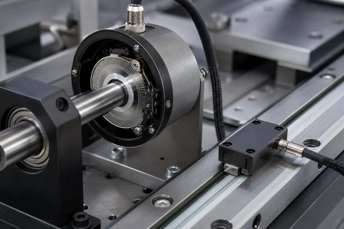
Representative product image. Confirm appearance and specifications with the manufacturer.

Product Specifications

Technical details and manufacturing context for Encoders

Definition
In a Multi-Axis Positioning System, encoders are critical feedback components that provide precise, real-time position and velocity data for each controlled axis. They enable closed-loop control by measuring the actual movement of motors or linear actuators, allowing the system controller to compare it to the commanded position and make necessary corrections for high-accuracy positioning, repeatability, and motion synchronization. Encoders are available in rotary and linear configurations, with incremental or absolute output types. They are used in applications such as CNC machines, robotics, and automated assembly lines where precise motion control is essential. The selection of an encoder depends on factors like required resolution, accuracy, output signal compatibility, supply voltage, shaft speed, operating temperature, ingress protection, shaft and body dimensions, connection type, moment of inertia, and weight. These parameters must be matched to the specific application and controller interface. For example, resolution is specified in pulses per revolution (PPR) and ranges from 100 to 5000 PPR, with higher PPR providing finer positioning. Accuracy ranges from ±0.01° to ±0.1°, depending on encoder type and mounting. Output signals can be TTL, HTL, 4–20 mA, or SSI, and supply voltage options are 5 V DC or 10–30 V DC. Maximum shaft speed is 3000–6000 rpm, and operating temperature ranges from -40°C to +85°C. Ingress protection is rated IP54 to IP67 per IEC 60529, with IP67 suitable for washdown environments. Shaft diameter ranges from 6 to 14 mm, body diameter from 36 to 58 mm, and connection types include cable, M12 connector, or terminal box. Moment of inertia is ≤ 50 g·cm², and weight is 0.2–0.5 kg. Materials used include aluminum alloy, stainless steel, optical glass, PCB, and plastic housing. Always verify model-specific values and standards with the legal manufacturer or supplier before procurement.
Working Principle
Encoders operate by generating a series of electrical pulses as a shaft rotates or a scale moves. In rotary encoders, a patterned disk attached to the shaft interrupts a light beam (optical) or varies a magnetic field (magnetic) as it spins. A sensor array detects these changes, producing digital square wave signals (incremental) or a unique digital code for each position (absolute). Linear encoders use a similar principle with a stationary read head scanning a graduated scale. The controller counts pulses or reads the code to determine precise position, direction, and speed.
Common Materials
Aluminum alloy, Stainless steel, Optical glass, PCB (Printed Circuit Board), Plastic (housing)
Technical Parameters
ParameterTypical rangeNotes & selection driver
Resolution100–5000 PPRHigher PPR for finer positioning
Accuracy±0.01°–±0.1 °Depends on encoder type and mounting
Output SignalTTL, HTL, 4–20 mA, SSIChoose based on controller interface
Supply Voltage5 V DC, 10–30 V DCHTL typically 10–30 V, TTL 5 V
Max. Shaft Speed3000–6000 rpmHigher speeds may reduce accuracy
Operating Temperature-40–+85 °CExtended range for industrial use
Ingress ProtectionIP54–IP67IP67 for washdown environmentsIEC 60529
Shaft Diameter6–14 mmMust match coupling or bore
Body Diameter36–58 mmCompact sizes for limited space
Connection TypeCable, M12 connector, terminal boxM12 for quick disconnect
Moment of Inertia≤ 50 g·cm²Low inertia for dynamic response
Weight0.2–0.5 kgAffects mounting and vibration

Ranges are indicative industry figures for RFQ preparation, not a supplier commitment. Confirm every value and standard with the legal manufacturer before ordering.

Components / BOM
  • Code Disk / Scale Part
    The patterned element (disk for rotary, strip for linear) that creates the optical or magnetic pattern read by the sensor.
    Material: Optical glass, metal, or polymer film
  • Light Source / Magnetic Field Generator
    Generates the beam (LED) or field that is modulated by the code disk/scale.
    Material: LED assembly, magnet
  • Sensor Array
    Detects the modulated light or magnetic field and converts it into electrical signals.
    Material: Photodiodes, Hall-effect sensors
  • Signal Conditioning Circuitry
    Amplifies, shapes, and digitizes the raw sensor signals into clean output pulses or data words.
    Material: PCB with integrated circuits
  • Shaft / Bearing Assembly
    Provides mechanical interface and rotation for the code disk (rotary encoders).
    Material: Stainless steel, ceramic
  • Housing Part
    Protects internal components from environmental factors like dust, moisture, and physical damage.
    Material: Aluminum alloy, plastic

Applied To / Applications

This component is essential for the following industrial systems and equipment:

Industrial Ecosystem & Supply Chain Structure

Complementary Systems
Downstream Applications
Specialized Tooling

Application Fit & Sizing Matrix

Operational Limits
pressure: Typically not pressure-rated; standard atmospheric pressure operation
other spec: Vibration resistance: 10-2000 Hz at 10g, Shock resistance: 100g for 6ms, IP rating: IP40 to IP67 depending on model
temperature: -40°C to +85°C (operating), -55°C to +100°C (storage)
Media Compatibility
✓ Clean industrial air environments ✓ Dry manufacturing settings ✓ Controlled laboratory conditions
Unsuitable: High-pressure washdown or submerged applications without proper IP rating
Sizing Data Required
  • Resolution (pulses per revolution or counts per inch)
  • Shaft diameter and mounting configuration
  • Required output signal type (analog, digital, fieldbus protocol)

Reliability & Engineering Risk Analysis

Failure Mode & Root Cause
Signal degradation or loss
Cause: Contamination ingress (dust, oil, metal particles) on optical/read head surfaces, or LED/photodetector aging in optical encoders, leading to intermittent or complete loss of position feedback.
Mechanical wear or binding
Cause: Bearing failure due to improper mounting (misalignment, excessive axial/radial load), lack of lubrication, or seal degradation allowing contaminant entry, causing increased rotational resistance or shaft seizure.
Maintenance Indicators
  • Erratic or jumping position readings on the control display, often accompanied by drive fault alarms (e.g., following error).
  • Audible grinding, clicking, or increased rotational noise from the encoder housing during shaft rotation.
Engineering Tips
  • Ensure proper mounting alignment and adherence to specified shaft loading limits; use flexible couplings where applicable to isolate vibration and misalignment.
  • Implement regular preventive cleaning of encoder surfaces with approved, non-residue solvents and compressed air in contaminated environments, and verify seal integrity.

Indicative industry ranges for design and RFQ preparation. Confirm the exact figures and applicable standard with the manufacturer before specifying.

Compliance & Manufacturing Standards

Applicable Standards
ISO 9409-1:2004 (Mechanical interfaces for modular robots) ANSI/B11.19-2019 (Performance criteria for safeguarding) DIN 43650 (Electrical connectors for industrial applications)

Quoted from the published standard.

Manufacturing Precision
  • Shaft runout: +/-0.01mm
  • Mounting flange perpendicularity: 0.05mm
Quality Inspection
  • IP rating validation test (dust/water ingress protection)
  • Electrical signal accuracy verification (pulse count/phase alignment)

Manufacturers of Encoders

Manufacturer profiles associated with Encoders.

Sourcing Encoders from China?
Tell us your specification and target quantity — we will match it against manufacturer records and come back with the factories that fit.
Request manufacturers We manufacture this

Manufacturer listings support early research and capability understanding. They are not certification, ranking, or transaction guarantees.

Technical documentation
Request current drawings, revision history, and a signed specification sheet.
Manufacturing capability
Verify equipment lists, process limits, capacity, and representative production evidence.
Inspection readiness
Confirm test methods, calibrated equipment, sampling plans, and traceable reports.
Supplier transparency
Check the legal entity, factory address, ownership, certifications, and direct contacts.

CNFX does not score or rank suppliers. Buyers must verify all claims and documents with the legal manufacturer before ordering.

Supply Chain Compatible Machinery & Devices

Automated Powder Coating System

Integrated industrial system for applying dry powder coatings to metal substrates.

Explore Specs →
Centrifugal Pump Impeller

The centrifugal pump impeller is a critical rotating component that converts mechanical energy from the motor into kinetic energy in fluid systems.

Explore Specs →
High-Precision CNC Laser Cutting Machine

Computer-controlled industrial machine using focused laser beams to cut sheet metal with micron-level accuracy.

Explore Specs →
Industrial-Grade Hydraulic Cylinder Piston Rod

This industrial-grade piston rod is a precision-ground cylindrical component designed for use in hydraulic cylinders.

Explore Specs →

Frequently Asked Questions

What is the difference between incremental and absolute encoders?

Incremental encoders generate pulses that indicate relative position changes; the controller counts pulses to determine position, but loses absolute position on power loss. Absolute encoders provide a unique digital code for each position, so they retain position information even after power is removed, allowing immediate position recovery without homing.

How do I choose the right resolution for my application?

Resolution is specified in pulses per revolution (PPR) for rotary encoders. Higher PPR provides finer positioning but may require higher bandwidth from the controller. Consider the required positioning accuracy and the maximum speed of the axis. For example, a range of 100–5000 PPR is common; select a value that meets your accuracy needs without exceeding the controller's counting capability.

What output signals are available and how do they interface with controllers?

Common output signals include TTL (5 V), HTL (10–30 V), 4–20 mA analog, and SSI (synchronous serial interface). The choice depends on the controller's input interface and the distance between encoder and controller. TTL is suitable for short distances, HTL for longer runs with higher noise immunity, and SSI for absolute encoders requiring digital data transfer.

What environmental factors should I consider when selecting an encoder?

Consider operating temperature range (-40°C to +85°C), ingress protection (IP54 to IP67), and potential exposure to washdown or dust. IP67 is recommended for harsh environments. Also, verify that the encoder's materials (e.g., aluminum, stainless steel, optical glass) are compatible with any chemicals or moisture in the application.

Data Basis

Editorial classification, named public sources where available, and source-reviewed manufacturer records.

Preliminary Technical Classification
This page supports structured research, RFQ preparation, and supplier evaluation. It does not replace buyer-led supplier qualification, standards review, or technical approval.
Buyer enquiry

Request manufacturing insight for Encoders

Ask for use case, specification boundaries, supplier type, and RFQ preparation information for this product.

Where it goes
Straight to the CNFX editorial desk, and to the manufacturer if this product is linked to a claimed profile. Nothing is broadcast to a supplier list.
Your details stay here
We do not sell or rent enquiry data, and we do not add you to a mailing list. Used only to answer this request.
No commission, no middleman
CNFX is a directory. We take no cut of any order and never negotiate on a supplier's behalf.
What we don't claim
A listing is not an endorsement. Qualify every supplier and verify every figure yourself before ordering.

Your business information is used only to process this request.

Thank you! Your message has been sent. We'll respond within 1–3 business days.
Sorry, we couldn't send your message. Please try again, or email us at contact@cnfx.com.

Need to Manufacture Encoders?

Compare manufacturer profiles with relevant product and process capability.

Previous Product
Encoder/Feedback Device
Next Product
End Effector
Get QuotesChat