Editorial Technical Reference

Signal Conditioning Circuitry

This page explains how Signal Conditioning Circuitry is classified within Computer, Electronic and Optical Product Manufacturing. Technical values and manufacturer relationships are research references; confirm the current specification and supplier evidence for each order.

Technical Definition & Core Assembly

Electronic circuitry that processes raw signals from optical sensors to prepare them for further analysis or conversion.
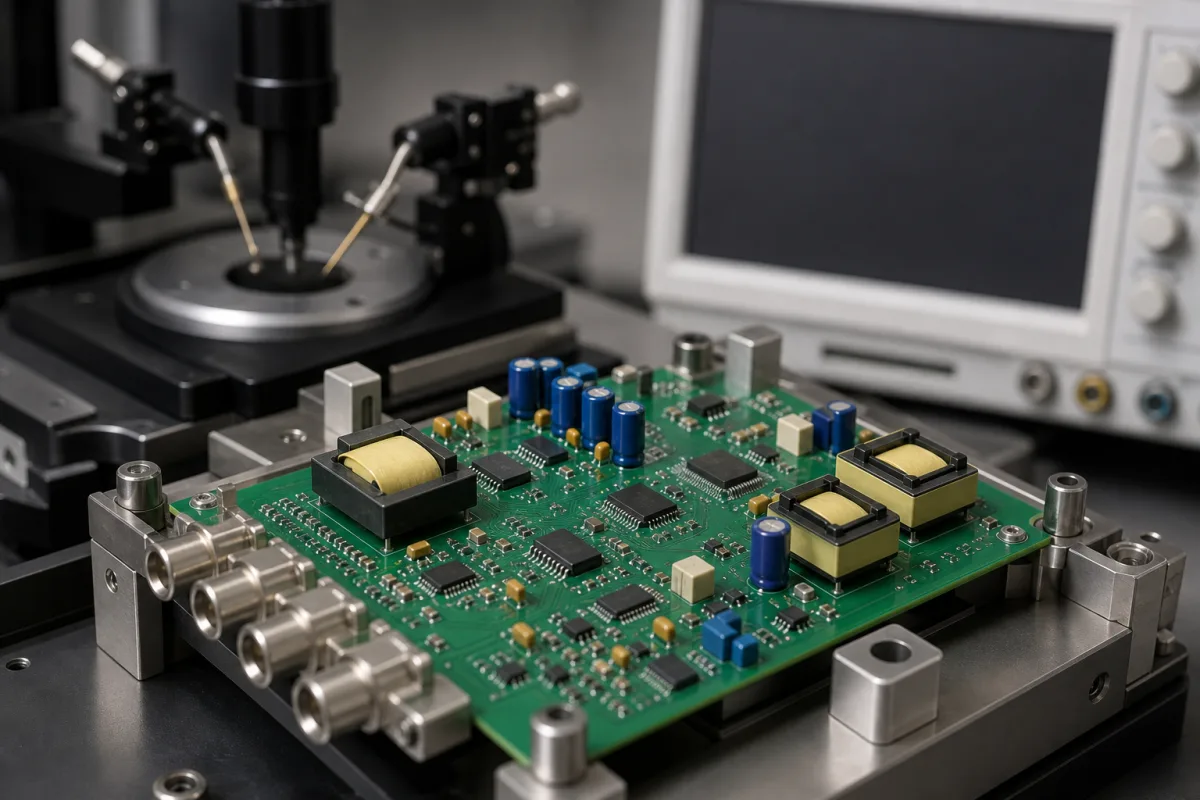
Representative product image. Confirm appearance and specifications with the manufacturer.

Product Specifications

Technical details and manufacturing context for Signal Conditioning Circuitry

Definition
Signal conditioning circuitry is an essential electronic component within optical sensor arrays that amplifies, filters, linearizes, and converts the low-level, often noisy analog signals from individual photodetectors into clean, standardized signals suitable for analog-to-digital conversion and subsequent digital processing. It ensures signal integrity, improves signal-to-noise ratio, and provides impedance matching between the sensor and the data acquisition system. This circuitry is typically used in industrial applications where optical sensors must interface with programmable logic controllers (PLCs), data acquisition systems (DAQs), or other control equipment. The product is designed as a compact module with a footprint of 50×25×10 mm and a weight of ≤50 g, making it suitable for PCB mounting. It operates over a wide input voltage range of 9–36 V DC and provides both voltage and current outputs: 0–10 V and 4–20 mA, respectively. The bandwidth is 0–100 kHz, sufficient for most optical sensors. Gain accuracy is ±0.5%, and input offset voltage is ±1 mV, critical for measurement accuracy. The circuitry is rated for industrial temperature ranges: operating from -40 to 85 °C and storage from -55 to 125 °C, with relative humidity up to 95% non-condensing. It offers ingress protection from IP54 to IP65, ensuring dust and water resistance. Supply current is ≤50 mA, and galvanic isolation of 1500 V DC is provided for safety. The product is constructed using semiconductor (silicon), copper, FR-4 PCB substrate, and solder. All listed parameters are reference ranges and must be verified for the specific model and application with the legal manufacturer or supplier.
Working Principle
The circuitry typically receives a weak current or voltage signal from a photodetector (e.g., photodiode). It first amplifies the signal using operational amplifiers to a usable level. It then applies filtering (low-pass, band-pass) to remove electrical noise and unwanted frequency components. Additional stages may include linearization to correct for sensor non-linearity, offset adjustment, and sometimes conversion to a different signal form (e.g., current-to-voltage). The output is a conditioned analog signal ready for the ADC.
Common Materials
Semiconductor (Silicon), Copper, FR-4 (PCB substrate), Solder
Technical Parameters
ParameterTypical rangeNotes & selection driver
Input Voltage9–36 V DCWide input range for industrial power supplies
Output Voltage0–10 VAnalog output for PLC/DAQ
Output Current4–20 mACurrent loop for noise immunity
Bandwidth0–100 kHzSufficient for most optical sensors
Gain Accuracy±0.5 %Critical for measurement accuracy
Input Offset Voltage±1 mVLow offset for precision
Operating Temperature-40–85 °CIndustrial temperature rangeIEC 60068-2-1/2
Storage Temperature-55–125 °CExtended storage capabilityIEC 60068-2-1/2
Relative Humidity0–95 % RHNon-condensingIEC 60068-2-78
Ingress ProtectionIP54–IP65Dust and water resistanceIEC 60529
Supply Current≤50 mALow power consumption
Isolation Voltage1500 V DCGalvanic isolation for safetyIEC 61010-1
Dimensions50×25×10 mmCompact module footprint
Weight≤50 gLightweight for PCB mounting

Ranges are indicative industry figures for RFQ preparation, not a supplier commitment. Confirm every value and standard with the legal manufacturer before ordering.

Components / BOM
  • Operational Amplifier (Op-amp) Part
    Amplifies the weak sensor signal to a higher voltage level.
    Material: Semiconductor (Silicon)
  • Filter Network (RC/LC) Part
    Removes high-frequency noise and unwanted signal components from the amplified signal.
    Material: Resistors (Carbon/Film), Capacitors (Ceramic/Film)
  • Printed Circuit Board (PCB)
    Provides the physical platform and electrical connections for all circuit components.
    Material: FR-4 (Glass-reinforced epoxy laminate)
  • Linearization and Offset Stage Optional
    Straightens the sensor curve and trims zero offset before the signal goes to the ADC.

Applied To / Applications

This component is essential for the following industrial systems and equipment:

Industrial Ecosystem & Supply Chain Structure

Complementary Systems
Downstream Applications
Specialized Tooling

Application Fit & Sizing Matrix

Operational Limits
pressure: Not applicable (electronic component)
other spec: Input signal range: 0-10V or 4-20mA, Power supply: 12-24VDC
temperature: -40°C to +85°C
Media Compatibility
✓ Clean air environments ✓ Laboratory settings ✓ Industrial control cabinets
Unsuitable: High EMI/RFI environments without proper shielding
Sizing Data Required
  • Sensor output signal type and range
  • Required output signal format for downstream systems
  • Environmental protection rating (IP/NEMA) needed

Reliability & Engineering Risk Analysis

Failure Mode & Root Cause
Signal Drift
Cause: Component aging (e.g., resistor/capacitor degradation), temperature fluctuations, or power supply instability affecting calibration.
Noise Amplification
Cause: Poor grounding/shielding, electromagnetic interference (EMI), or degraded/faulty operational amplifiers introducing unwanted signals.
Maintenance Indicators
  • Erratic or unstable output readings on connected displays/controllers
  • Audible humming/buzzing from circuitry or intermittent signal dropout
Engineering Tips
  • Implement regular calibration and environmental monitoring (temperature/humidity) to maintain signal integrity.
  • Use shielded cables, proper grounding techniques, and periodic inspection of connectors/components for corrosion/wear.

Indicative industry ranges for design and RFQ preparation. Confirm the exact figures and applicable standard with the manufacturer before specifying.

Compliance & Manufacturing Standards

Applicable Standards
IEC 61000-6-2: Electromagnetic compatibility - Generic standards - Immunity for industrial environments IEC 61131-2: Programmable controllers - Equipment requirements and tests EN 55011: Industrial, scientific and medical equipment - Radio-frequency disturbance characteristics - Limits and methods of measurement

Quoted from the published standard.

Manufacturing Precision
  • Resistor tolerance: +/-0.1% for precision signal conditioning
  • Temperature coefficient: +/-5 ppm/°C for critical components
Quality Inspection
  • Signal integrity verification through oscilloscope analysis
  • Environmental stress testing (temperature cycling, humidity, vibration)

Manufacturers of Signal Conditioning Circuitry

Manufacturer profiles associated with Signal Conditioning Circuitry.

Sourcing Signal Conditioning Circuitry from China?
Tell us your specification and target quantity — we will match it against manufacturer records and come back with the factories that fit.
Request manufacturers We manufacture this

Manufacturer listings support early research and capability understanding. They are not certification, ranking, or transaction guarantees.

Technical documentation
Request current drawings, revision history, and a signed specification sheet.
Manufacturing capability
Verify equipment lists, process limits, capacity, and representative production evidence.
Inspection readiness
Confirm test methods, calibrated equipment, sampling plans, and traceable reports.
Supplier transparency
Check the legal entity, factory address, ownership, certifications, and direct contacts.

CNFX does not score or rank suppliers. Buyers must verify all claims and documents with the legal manufacturer before ordering.

Supply Chain Compatible Machinery & Devices

Modular Industrial Edge Computing Device

This modular industrial edge computing device is a ruggedized system designed for deployment in harsh industrial environments to perform real-time data processing, analytics, and control functions at the network edge.

Explore Specs →
Industrial Smart Camera Module

The Industrial Smart Camera Module is a compact, self-contained vision processing unit designed for integration into industrial machinery and production lines.

Explore Specs →
Surface Mount Resistor

Passive electronic component for current limiting and voltage division in circuits

Explore Specs →
Surface Mount Capacitor

A surface mount capacitor is a fundamental electronic component used for energy storage, filtering, coupling, and decoupling in electronic circuits.

Explore Specs →

Frequently Asked Questions

What is the typical input voltage range for this signal conditioning circuitry?

The input voltage range is 9–36 V DC, suitable for industrial power supplies. However, verify the exact range for your specific model with the manufacturer.

What output signals does this circuitry provide?

It provides both voltage output (0–10 V) and current output (4–20 mA) for compatibility with PLCs and DAQs. Confirm the output configuration for your application.

What is the operating temperature range?

The operating temperature range is -40 to 85 °C, with storage from -55 to 125 °C. These are reference values; check the datasheet for your model.

Does this circuitry provide galvanic isolation?

Yes, it provides isolation voltage of 1500 V DC per IEC 61010-1. This is a safety feature, but always verify compliance for your specific installation.

Data Basis

Editorial classification, named public sources where available, and source-reviewed manufacturer records.

Preliminary Technical Classification
This page supports structured research, RFQ preparation, and supplier evaluation. It does not replace buyer-led supplier qualification, standards review, or technical approval.
Buyer enquiry

Request manufacturing insight for Signal Conditioning Circuitry

Ask for use case, specification boundaries, supplier type, and RFQ preparation information for this product.

Where it goes
Straight to the CNFX editorial desk, and to the manufacturer if this product is linked to a claimed profile. Nothing is broadcast to a supplier list.
Your details stay here
We do not sell or rent enquiry data, and we do not add you to a mailing list. Used only to answer this request.
No commission, no middleman
CNFX is a directory. We take no cut of any order and never negotiate on a supplier's behalf.
What we don't claim
A listing is not an endorsement. Qualify every supplier and verify every figure yourself before ordering.

Your business information is used only to process this request.

Thank you! Your message has been sent. We'll respond within 1–3 business days.
Sorry, we couldn't send your message. Please try again, or email us at contact@cnfx.com.

Need to Manufacture Signal Conditioning Circuitry?

Compare manufacturer profiles with relevant product and process capability.

Previous Product
XY Positioning Stage
Last Product
Get QuotesChat