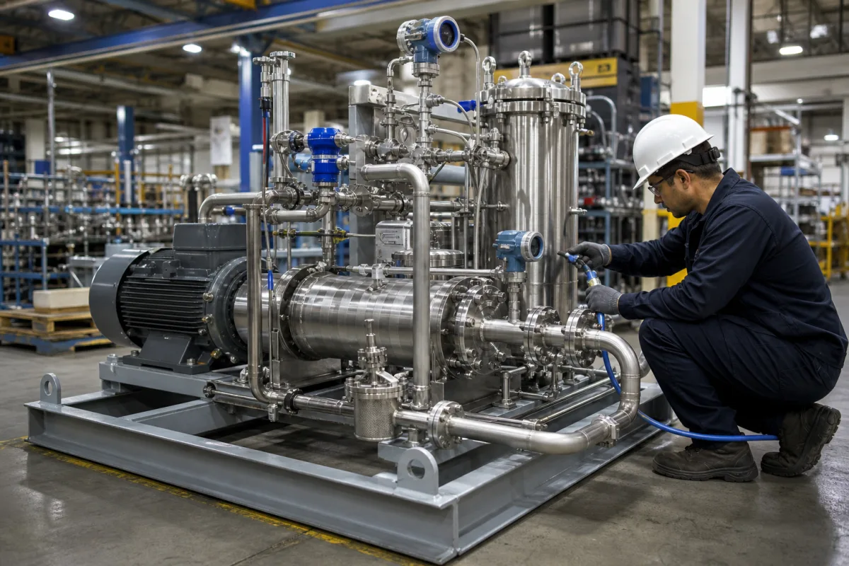
Feed pump module for heavy fuel oil: the supply and circulating (booster) pump skid between the service tank and a diesel engine
Skid-mounted supply and circulating pumps that feed heated heavy fuel oil to diesel engines · about 4 bar from the supply pumps, 8 bar or more at the engine inlet, circulation at three times consumption, and viscosity held at 12–18 cSt
In a diesel plant burning heavy fuel oil, the feed pump module is the packaged skid that takes fuel from the service tank, raises it to a low supply pressure, then circulates it at a higher pressure through heaters, a filter and a viscosity controller to the engines' injection pumps and back. It is bought as one tested unit with redundant pump pairs, and its job is to hold flow, pressure and viscosity at the engine inlet whatever the load.
Pressurised fuel oil feed pump modules (fuel oil supply or booster units) for heavy fuel oil and distillate service on marine and stationary diesel engines: supply pumps, circulating (booster) pumps, pressure control and relief valves, preheaters, coolers, filters, viscosity control, venting and flow metering on one skid. Air-operated and electric diaphragm transfer pumps are covered on the Diaphragm pump page. Water-treatment dosing skids are covered on the Chemical dosing pump skid page, ceramic piston dispensing pumps on the Precision metering pump for filling and dispensing page, and general multi-pump centrifugal skids on the Pumping system page. Boiler feedwater pumps, engine-mounted fuel injection pumps and separate fuel filters have their own pages; fuel oil separators and transfer pumps are outside this page. High-pressure rails downstream of the injection pump are covered on the Common rail page, reagent metering skids for continuous reactors on the Reagent feed system page, solvent-dosing viscosity control for coating tanks on the Automated viscosity control and mixing system page, and DEF supply modules on the Exhaust aftertreatment system page.
CNFX editorial research · Sources checked October 12, 2026 · 4 sources
Two pressure stages: about 4 bar from the supply pumps, 8 bar or more at the engine inlet
MAN Energy Solutions' project guide for its L21/31 and related four-stroke gensets describes a low-pressure supply system in which one of the redundant, electrically driven supply pumps delivers fuel at an adjusted pressure of approximately 4 bar to the circulation system. The fuel, mixed with the return from the engines, then goes to one of the redundant circulating pumps and on through a preheater, a diesel cooler and viscosity control. [1]
The same guide sets the circulation pressure at 8–9 bar at the inlet of a MAN two-stroke propulsion engine, with a back-pressure of about 4 bar from the supply system, and says fuel pressure for gensets must be at least 8 bar and may be up to 16 bar, recommending that fuel be distributed to the gensets before the main engine. An external relief valve must be set to at least 10 bar so it does not interfere with the engine's internal valve, and pressure dampers may be needed if the system shows unexpected pressure fluctuations. [1]
When commissioning, MAN sets the engine inlet pressure with the pressure control valve parallel to the supply pump at a set point of about 4 bar, and warns that the safety valves on the supply and circulating pumps protect the pumps only and must not be used to set system or supply pressure. [1]
Wärtsilä's marine encyclopedia defines a fuel oil unit as the equipment that prepares fuel for a boiler or engine, including the pumps, filters and heaters handling oil above 0.18 N/mm² (1.8 bar). [2] Editorial calculation: on MAN's figures, the circulating pumps lift the fuel by roughly 4–5 bar above the supply stage for a two-stroke inlet (8–9 bar minus about 4 bar), and by up to about 12 bar for gensets at the 16 bar ceiling. [1]
Give the module builder the engine types and numbers on the system, the required inlet pressure for each, the back-pressure in the return, and where the relief and pressure control valves sit.
02
Pump capacity: supply at full-load consumption, circulation at three times it
MAN sizes the supply pumps for at least the fuel consumption of all engines in the system at 100% load, and the circulating pumps for at least three times that consumption; the circulating pumps keep running even when engines are stopped, so heated fuel keeps the injection pumps ready to start. [1]
Editorial calculation: in each row the circulating capacity is very close to three times the supply capacity (0.89 ÷ 0.30 ≈ 3.0; 1.76 ÷ 0.59 ≈ 3.0), matching the guide's sizing rule. A plant with three 6-cylinder gensets would need supply pumps of at least about 1.2 m³/h (3 × 0.39) and circulating pumps of about 3.5 m³/h (3 × 1.18), before any main engine is added. [1]
For distillate, MAN recommends a separate line from the service tank through a distillate booster pump sized at least three times the distillate consumed at 100% load, so the gensets can change fuel independently of the propulsion engine. [1]
State the full-load consumption of every engine the module feeds, whether duty and standby pumps are required on both stages, and whether a separate distillate circuit is needed.
03
Heating and viscosity control on the skid
Bosch's US 8,839,764 B2 on heavy-oil common-rail systems notes that heavy oil is so much more viscous than diesel fuel that it must be heated above 80 °C before it can be pumped at all; in its system a primary feed pump delivers preheated fuel through a filter to a high-pressure pump that compresses it to above 1,400 bar. [4]
MAN prescribes an injection viscosity of 12–14 mm²/s, or 12–18 cSt for its genset types including the L21/31 and L28/32H, with the matching fuel temperature read from its viscosity-temperature diagram; for distillate it gives at least 2 cSt at the engine inlet, which may require a cooler. [1] Wärtsilä lists the parts of a fuel oil supply system as a supply flow meter, supply pumps, circulating pumps, preheaters, the final filter, a viscosity controller and a venting box, and notes that it can be delivered as a modular fuel oil supply unit, tested and ready for connection. [3]
MAN also sets a limit for the automatic back-flush filter in the feeder circuit: a filter surface load of 1 l/cm² per hour must not be exceeded. [1] Editorial calculation: if the 0.89 m³/h circulating flow of a 5-cylinder L21/31 passed that filter, it would need at least about 890 cm² of filter surface (890 l/h ÷ 1 l/cm²·h); confirm with the module builder which flow the filter actually sees.
Specify the fuel grades (HFO viscosity at 50 °C, distillate), the injection viscosity each engine needs, heater duty and medium (steam, thermal oil or electric), cooler for distillate, filter type and fineness.
04
Engine, fuel and pressure data for a fuel oil feed pump module
Paste it into your enquiry below or into an email to a maker, then replace every bracket.
Engines: [types; number; full-load fuel consumption each]
Fuels: [HFO grade and viscosity; distillate; changeover needs]
Pressures: [supply set point; required inlet pressure per engine; return back-pressure]
Pumps: [supply and circulating capacity; duty/standby; drive]
Conditioning: [preheater duty and medium; cooler; viscosity controller]
Filter: [type; fineness; surface area]
Skid: [flow meter; venting box; dimensions; class approval]
Explore company information and manufacturing capabilities, then discuss the scope of your project with a relevant supplier.
Share this page
Compiled and source-reviewed by the CNFX editorial team.
Each manufacturer above links to the page on that company's own website where the product is listed, with the date we checked it. How we source and review
· Page last updated 13 October 2026
Buyer questions
What pressure does a fuel oil supply pump deliver?
MAN's project guide gives approximately 4 bar from the supply pumps into the circulation system. [1]
How large should the circulating pumps be?
MAN sizes them for at least three times the fuel consumption of all engines at 100% load; the supply pumps for at least that consumption. [1]
What pressure is needed at a genset fuel inlet?
At least 8 bar and up to 16 bar according to MAN; 8–9 bar at its two-stroke propulsion engine inlet. [1]
Why must heavy fuel oil be heated in the module?
Bosch notes it must be above 80 °C to be pumped at all, and MAN prescribes 12–18 cSt at injection for its gensets. [4][1]
Sources and what still needs a direct check
Sources checked 2026-10-12. MAN Energy Solutions' genset project guide (L21/31 and related engines), two Wärtsilä encyclopedia entries on fuel oil units and supply systems, and a Robert Bosch patent on heavy-oil common-rail fuel supply.