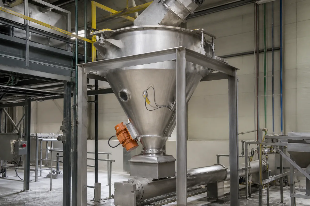
Externally vibrated stainless cone hopper over a screw feeder: sizing and placing the bin vibrator, checking the cone angle and outlet, and drawing evenly into the screw
A stainless conical hopper that holds powder or granules over a screw feeder · sized by wall angle and outlet diameter so the solids keep moving, then helped by a bin vibrator and a screw that draws evenly from the whole inlet
A feed hopper of this kind is a short stainless vessel: a cylindrical or square top that receives powder or granules from a chute or bag dump, a converging cone, and an outlet flanged to a screw feeder that meters the material onward. Whether it delivers steadily depends on three design decisions. The cone walls must be steep and smooth enough for the material to slide, so the whole contents move and nothing is left stagnant. The outlet must be wide enough that the material cannot form a stable arch. And the screw below must take material from the full length of its inlet rather than only from the back. This page starts with the rotary vibrator bolted to the cone, then the cone and outlet checks that come from flow testing, then the screw inlet below.
Rigid stainless conical feed hoppers (surge hoppers) for powders and granules, fitted with an external rotary electric bin vibrator on the cone and discharging into a screw feeder: vibrator force, speed, mounting height and number, and the wall-angle and outlet checks made alongside it. Vibrator motors as products are covered on the Vibration motor (industrial vibrator motor) page; hoppers with flexible paddle-massaged walls or internal agitators are covered on the Agitated ingredient feed hopper for a screw feeder page; silos and storage bins designed from measured flow properties, with their structural loads, on the Bulk storage hopper (bins and silos) page; screw pitch, drawdown and drive in depth on the Screw feeder page. Feeders and hoppers for coarse bulk material on vibrating trays, with their gates and skirtboards, are covered on the Vibrating feeder page; linear tracks and escapements after parts feeders on the Feeding mechanism between bowl feeder and assembly page; two-shaft vibration exciters on the Geared two-shaft vibration exciter page.
CNFX editorial research · Sources checked October 13, 2026 · 4 sources
The bin vibrator on the cone: one pound of force per ten pounds of material in the sloped section, mounted a third of the way up
Renold sizes its AJAX rotary electric vibrators for bins, hoppers and silos from the weight of product in the sloped wall portion of the vessel, at a ratio of ten pounds of product to one pound of vibrator force output. [3]
Editorial calculation with the Renold cone formula, for an assumed hopper with a 1.5 m top diameter, a 0.3 m outlet and walls at 60° from horizontal: vertical height = tan 60° × (0.75 − 0.15) m ≈ 1.04 m; V = 1.0472 × 1.04 × (0.5625 + 0.1125 + 0.0225) ≈ 0.76 m³. At an assumed bulk density of 500 kg/m³ the cone holds about 380 kg, so the 1 : 10 rule calls for about 38 kgf (roughly 0.37 kN) of vibrator force. [3] The dimensions and density are assumptions for illustration.
Renold also notes that dual counter-rotating vibrators can raise the material packed into a container by 20–50 % when used for densification. [3] Editorial note: compaction is the opposite of what a feed hopper needs, so a densifying arrangement is not a flow aid.
Renold flow-aid rule
Value
Force output against sloped-section product weight
1/3 of the total sloped distance from the discharge [3]
When two or three vibrators are needed
Product very difficult to flow, or more than 25 tons in the sloped portion; staggered at 90°, run intermittently on a timer, not simultaneously [3]
Volume in a conical section
V = 1.0472 × vertical height × (R² + R·r + r²), R and r the inlet and discharge radii [3]
State the bulk density, the cone dimensions and wall angle, and whether discharge is continuous or intermittent, so vibrator force, speed and mounting height can be set.
02
Wall angle and outlet diameter: mass flow with a 3° margin, and an outlet wider than the critical arching size
Chemical Engineering (2016) explains that in mass flow the whole bed moves on discharge, giving first-in, first-out flow, while in funnel flow a channel forms over the outlet and material stays stagnant at the walls as ratholes. Mass flow is reached by measuring wall friction (ASTM D6128) and calculating the minimum hopper angle from Jenike's design charts. [1]
The outlet size comes from two measured properties: the material's flow function (cohesive strength against consolidation pressure, from shear-cell tests) and the hopper's flow factor, which depends on the effective angle of internal friction, the hopper angle and the wall friction angle. Where the flow function lies below the flow-factor line, the arch stress always exceeds the material's strength and no minimum outlet is needed to prevent arching. [1][2]
Editorial note: the slot-width relation explains why a long rectangular hopper outlet can sit over a screw feeder inlet where a round outlet of the same width would arch; the screw then has to draw along the full slot, which is the subject of the last section.
Design value
Published figure
Source
Margin on the mass-flow angle for round or square outlets
At least 3° steeper than the theoretical mass-flow angle, so a small change in powder properties does not tip the hopper into funnel flow [1]
Chemical Engineering, 2016
Wedge (slotted-outlet) hoppers
Walls can be 10–12° less steep than a conical hopper needs; the slot must be at least three times as long as it is wide for that chart to apply [1]
A material with a critical arching diameter of 12 in. arches over 6 or 8 in. outlets and flows through 12 or 14 in. outlets [2]
Chemical Engineering, 2020
Slot width against round outlet
Minimum slot width in a wedge mass-flow hopper is about half the minimum circular outlet diameter for the same material [2]
Chemical Engineering, 2020
Materials suited to funnel flow
Free-flowing solids with particles of 1/4 in. or larger and little tendency to degrade [2]
Chemical Engineering, 2020
Angles used before flow testing
30° from vertical to save wall material, or 45° to save headroom [1]
Chemical Engineering, 2016
Give the material's wall friction angle on the chosen stainless finish, its flow function, and the outlet size or connection the feeder below requires; ask which angle and outlet the hopper was designed to and what margin was applied.
03
The screw under the outlet: flood-loaded inlet, flights that grow toward discharge, and a shroud at least two pitches long
KWS Manufacturing describes the screw feeder below a hopper as flood loaded (100 percent) at its inlet, with the design of the screw in the inlet area and the screw speed setting the feed rate. [4]
A screw with uniform outside diameter and constant pitch fills from the rear of the inlet first, which KWS says creates ratholing, stagnant material and possible bridging above the feeder. To draw evenly across the full inlet each flight must add available volume toward the discharge, by variable pitch, stepped pitch (KWS's example: 2 ft of 1/3 pitch then 2 ft of 2/3 pitch), a tapered outside diameter, or the Jenike & Johanson mass-flow screw with a tapered cone and short-pitch flights over the rear half of the inlet. [4]
The feeder needs a shroud for at least 2 pitches beyond the inlet so material does not flood past the screw; the last flight entering the shroud, the control pitch, sets the feed rate in cubic feet per hour per rpm. KWS gives screw speeds under 20 rpm as the example for heavy industrial screw feeders, and warns that start-up horsepower and torque can reach 2.5 times normal running values, with material factors above 4.0 for packed material under hopper pressure. [4]
If the feeder rises from the hopper, KWS states that screw feeders lose efficiency above 5° of incline, that U-troughs serve up to 15° and tubular housings above that, and that the inlet of an inclined feeder should not exceed twice the screw diameter in length. [4]
Give the outlet length and width, the feed rate range, the feeder incline, and the bulk density both as stored in the hopper and as metered.
04
What to send for a feed hopper over a screw feeder
Paste it into your enquiry below or into an email to a maker, then replace every bracket.
Material: [name; particle size; bulk density stored and metered; moisture]
Flow tests: [wall friction angle on the contact finish; flow function, if measured]
Hopper: [working volume; top size; cone or wedge; outlet size]
Flow aids: [vibrator; level sensors; sight glass]
Feeder: [rate range; screw type; incline; outlet connection]
Hygiene: [contact material; surface finish; cleaning method]
Explore company information and manufacturing capabilities, then discuss the scope of your project with a relevant supplier.
Share this page
Compiled and source-reviewed by the CNFX editorial team.
Each manufacturer above links to the page on that company's own website where the product is listed, with the date we checked it. How we source and review
· Page last updated 13 October 2026
Buyer questions
What safety margin should be added to the mass-flow hopper angle?
Chemical Engineering recommends at least 3° steeper than the theoretical mass-flow angle for round or square outlets. [1]
How big a vibrator does a hopper need?
Renold's rule is one pound of vibrator force for every ten pounds of product in the sloped section, with one vibrator mounted a third of the sloped distance up from the discharge. [3]
Why does a constant-pitch screw under a hopper cause ratholes?
KWS explains that it fills from the rear of the inlet first; flights must add volume toward the discharge to draw evenly from the whole inlet. [4]
How much smaller can a slot outlet be than a round one?
For the same material, Chemical Engineering puts the minimum slot width in a wedge mass-flow hopper at about half the minimum round outlet diameter. [2]
Sources and what still needs a direct check
Sources checked 2026-10-13. Four sources: two Chemical Engineering articles on hopper design (2016) and outlet geometry and arching (2020), Renold's AJAX rotary electric vibrator guide, and KWS Manufacturing's engineering guide to screw feeders.