Editorial Technical Reference

Flame Sensor

This page explains how Flame Sensor is classified within Machinery and Equipment Manufacturing. Technical values and manufacturer relationships are research references; confirm the current specification and supplier evidence for each order.

Technical Definition & Core Assembly

A safety device that detects the presence or absence of a flame in a burner system.
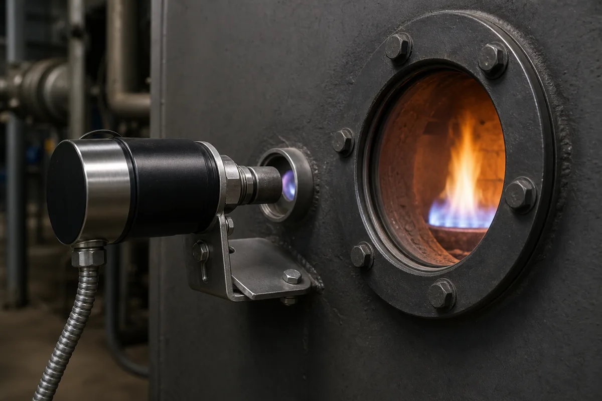
Flame Sensor in a manufacturing environment
Representative product image. Confirm appearance and specifications with the manufacturer.

Product Specifications

Technical details and manufacturing context for Flame Sensor

Definition
The Flame Sensor is a critical safety component used in burner assemblies within the machinery and equipment manufacturing industry. Its primary function is to continuously monitor the presence of a flame to ensure safe operation of the burner. By detecting the flame's optical, thermal, or electrical properties, the sensor sends a signal to the burner control system. When a flame is present, the control system maintains fuel flow; if flame failure occurs, the sensor triggers a safety shutdown to prevent hazardous conditions such as fuel accumulation or explosion. The sensor operates on principles such as ultraviolet (UV) radiation detection, infrared (IR) radiation detection, or flame rectification (ionization current). It converts the detected signal into an electrical output that the control system interprets. Typical specifications include a detection distance of 0.5 to 2.0 meters, a response time of ≤1 second, a spectral range of 300 to 1100 nanometers, a supply voltage of 24 V DC ±10%, an output signal of 4–20 mA, an operating temperature range of -40 to 85 °C, ingress protection ratings of IP65 to IP67 per IEC 60529, and a housing material of stainless steel 316 per ASTM A240. The weight ranges from 0.5 to 1.5 kg depending on housing size and options. These values are reference ranges and must be verified for the specific model and application with the legal manufacturer or supplier. The sensor is designed for industrial environments, with materials including stainless steel, ceramic, and quartz glass. Proper installation, calibration, and regular testing are essential to ensure reliable flame detection and system safety.
Working Principle
The Flame Sensor detects flame presence by sensing ultraviolet (UV) radiation, infrared (IR) radiation, or flame rectification (ionization current) generated by the flame. The sensor converts the detected signal into an electrical output, typically a 4–20 mA analog signal proportional to flame intensity. This output is interpreted by the burner control system to maintain fuel flow when flame is present or to initiate safety shutdown if flame failure occurs. The sensor's spectral range of 300–1100 nm covers UV to near-infrared, allowing detection of various flame types. The response time is ≤1 second, ensuring rapid reaction to flame loss. The sensor operates within a temperature range of -40 to 85 °C and is protected against dust and water jets with IP65–IP67 ratings.
Common Materials
Stainless Steel, Ceramic, Quartz Glass
Technical Parameters
ParameterTypical rangeNotes & selection driver
Detection Distance0.5–2.0 mMaximum distance for reliable flame detection
Response Time≤1 sTime to signal flame presence or absence
Spectral Range300–1100 nmCovers UV to near-infrared for various flame types
Supply Voltage24 ±10% V DCTypical industrial control voltage
Output Signal4–20 mAAnalog output proportional to flame intensity
Operating Temperature-40–85 °CAmbient temperature range for electronics
Ingress ProtectionIP65–IP67Dust-tight and protected against water jetsIEC 60529
Material316 SSCorrosion-resistant stainless steel housingASTM A240
Weight0.5–1.5 kgDepends on housing size and options

Ranges are indicative industry figures for RFQ preparation, not a supplier commitment. Confirm every value and standard with the legal manufacturer before ordering.

Components / BOM
  • Sensor Element Part
    Detects flame radiation or ionization current
    Material: Quartz/UV Tube or Metal Rod
  • Housing Part
    Protects internal components from heat and environmental conditions
    Material: Stainless Steel
  • Electrical Connector Part
    Provides interface for signal transmission to control system
    Material: Brass/Stainless Steel
  • Signal Output Converter
    Turns the raw detector output into the 4–20 mA signal the burner controller reads.

Applied To / Applications

This component is essential for the following industrial systems and equipment:

Industrial Ecosystem & Supply Chain Structure

Complementary Systems
Downstream Applications
Specialized Tooling

Application Fit & Sizing Matrix

Operational Limits
pressure: 0 to 1 bar (atmospheric to slight positive pressure)
other spec: UV/IR detection range: 185-260 nm (UV), 700-1100 nm (IR); Response time: <3 seconds; Power: 24V DC ±10%
temperature: -40°C to 85°C (operating), up to 120°C (short-term exposure)
Media Compatibility
✓ Natural gas combustion systems ✓ Propane burner applications ✓ Oil-fired heating systems
Unsuitable: High particulate environments (e.g., coal dust, heavy soot)
Sizing Data Required
  • Burner flame size and shape
  • Required detection distance (sensor-to-flame)
  • Ambient light interference level

Reliability & Engineering Risk Analysis

Failure Mode & Root Cause
Lens contamination
Cause: Accumulation of soot, dust, or oil deposits on the optical surface, blocking or scattering the flame signal, often due to poor combustion, inadequate air filtration, or proximity to dirty environments.
Sensor drift or calibration loss
Cause: Degradation of internal components (e.g., photocells, UV tubes) over time from thermal cycling, prolonged exposure to high temperatures, or aging electronics, leading to inaccurate flame detection thresholds.
Maintenance Indicators
  • Intermittent or false flame detection (e.g., burner cycling on/off unexpectedly, alarms without flame loss)
  • Visible buildup or discoloration on the sensor lens or housing, indicating contamination or overheating
Engineering Tips
  • Implement regular lens cleaning with appropriate solvents (e.g., isopropyl alcohol) and soft materials to prevent scratching, combined with inspection during routine maintenance shutdowns.
  • Ensure proper sensor alignment and mounting to avoid direct exposure to excessive heat or vibration, and verify calibration annually using manufacturer-recommended test procedures.

Indicative industry ranges for design and RFQ preparation. Confirm the exact figures and applicable standard with the manufacturer before specifying.

Compliance & Manufacturing Standards

Applicable Standards
ISO 23550:2011 (Safety and control devices for gas burners and gas-burning appliances) ANSI Z21.20 (Automatic gas ignition systems and components) EN 298:2012 (Automatic burner control systems for burners and appliances burning gaseous or liquid fuels)

Quoted from the published standard.

Manufacturing Precision
  • Optical alignment: +/- 0.5° angular deviation
  • Response time: +/- 10% of specified value (typically 2-4 seconds)
Quality Inspection
  • UV/IR spectral response verification test
  • Environmental durability test (temperature cycling, vibration, humidity)

Manufacturers of Flame Sensor

1 company lists this product among what they make. Company figures are quoted from each company's own website; every card states where the relationship came from.

Winsen Electronics Technology Co., Ltd.
Zhengzhou, Henan, CN
Listed on the company's own website · profile compiled by CNFX from public sources
Listed there as: “Flame sensor”
View source page ↗ winsen-sensor.com · checked 2026-09-10

Manufacturer listings support early research and capability understanding. They are not certification, ranking, or transaction guarantees.

Share this page
Technical documentation
Request current drawings, revision history, and a signed specification sheet.
Manufacturing capability
Verify equipment lists, process limits, capacity, and representative production evidence.
Inspection readiness
Confirm test methods, calibrated equipment, sampling plans, and traceable reports.
Supplier transparency
Check the legal entity, factory address, ownership, certifications, and direct contacts.

CNFX does not score or rank suppliers. Buyers must verify all claims and documents with the legal manufacturer before ordering.

Supply Chain Compatible Machinery & Devices

Hydraulic Press

Industrial machine using hydraulic pressure to compress, form, or assemble materials

Explore Specs →
Heavy-Duty CNC Plasma Cutting Machine

The Heavy-Duty CNC Plasma Cutting Machine is a standalone industrial device designed for cutting conductive metals such as steel, stainless steel, aluminum, and copper alloys.

Explore Specs →
Automated Powder Coating System

Integrated industrial system for applying dry powder coatings to metal substrates.

Explore Specs →
Centrifugal Pump Impeller

The centrifugal pump impeller is a critical rotating component that converts mechanical energy from the motor into kinetic energy in fluid systems.

Explore Specs →

Frequently Asked Questions

What is the typical detection distance of a flame sensor?

The detection distance is typically 0.5 to 2.0 meters, but this depends on the flame type, sensor model, and installation conditions. Always verify the specific model's rated distance with the manufacturer.

How does the flame sensor communicate with the burner control system?

The sensor provides an analog output signal of 4–20 mA, which is proportional to flame intensity. This signal is interpreted by the control system to determine flame presence and adjust fuel flow accordingly.

What environmental conditions can the flame sensor withstand?

The sensor is designed for industrial environments with an operating temperature range of -40 to 85 °C and ingress protection ratings of IP65 to IP67, meaning it is dust-tight and protected against water jets. However, actual ratings may vary by model.

What maintenance is required for a flame sensor?

Regular cleaning of the sensor lens and checking for proper alignment are recommended. Also, verify that the sensor's response time and output signal remain within specifications. Always follow the manufacturer's maintenance guidelines.

Data Basis

Editorial classification, named public sources where available, and source-reviewed manufacturer records.

Preliminary Technical Classification
This page supports structured research, RFQ preparation, and supplier evaluation. It does not replace buyer-led supplier qualification, standards review, or technical approval.
Buyer enquiry

Request manufacturing insight for Flame Sensor

Ask for use case, specification boundaries, supplier type, and RFQ preparation information for this product.

Where it goes
Straight to the CNFX editorial desk, and to the manufacturer if this product is linked to a claimed profile. Nothing is broadcast to a supplier list.
Your details stay here
We do not sell or rent enquiry data, and we do not add you to a mailing list. Used only to answer this request.
No commission, no middleman
CNFX is a directory. We take no cut of any order and never negotiate on a supplier's behalf.
What we don't claim
A listing is not an endorsement. Qualify every supplier and verify every figure yourself before ordering.

Your business information is used only to process this request.

Thank you! Your message has been sent. We'll respond within 1–3 business days.
Sorry, we couldn't send your message. Please try again, or email us at [email protected].

Need to Manufacture Flame Sensor?

Compare manufacturer profiles with relevant product and process capability.

Previous Product
Z-axis Ram/Spindle
Last Product
Get QuotesChat