Editorial Technical Reference

Burner Assembly

This page explains how Burner Assembly is classified within Basic Metal Manufacturing. Technical values and manufacturer relationships are research references; confirm the current specification and supplier evidence for each order.

Technical Definition & Core Assembly

A combustion system component that generates controlled flame for heating applications in industrial preheating stations.

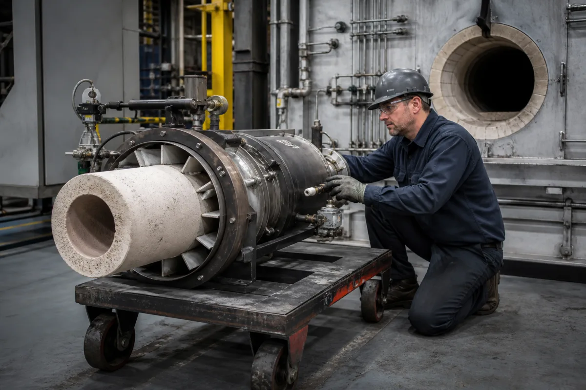
Representative product image. Confirm appearance and specifications with the manufacturer.

Product Specifications

Technical details and manufacturing context for Burner Assembly

Definition
The Burner Assembly is a critical component of the Automated Ladle Preheating Station, responsible for generating and maintaining a controlled flame to preheat ladles before molten metal transfer. It ensures uniform heating to prevent thermal shock and maintain optimal ladle temperature for efficient metal handling in foundry and steelmaking operations. The assembly mixes fuel (typically natural gas or propane) with air in precise ratios, ignites the mixture to create a stable flame, and directs the thermal energy toward the ladle surface. It includes fuel delivery, air supply, ignition, flame monitoring, and safety control systems working in coordination. Constructed from stainless steel, refractory ceramics, and high-temperature alloys, the assembly is designed for durability in harsh industrial environments. Key parameters include thermal capacity (0.5–5.0 kW), fuel consumption rate (40–400 m³/h), air-to-fuel ratio (1.05–1.15), operating temperature range (-20 to 85 °C), operating pressure (1.0–1.6 MPa), fuel supply pressure (0.1–0.4 MPa), combustion efficiency (≥92%), NOx emission (≤80 mg/Nm³), CO emission (≤50 mg/Nm³), ignition voltage (15–20 kV), electrical power (0.5–2.0 kW), supply voltage (220–240 V AC), material grade (SS 304/316), and weight (15–60 kg). These values are reference ranges and must be verified for the specific model and application. Standards such as ISO 13578, ISO 6976, IEC 60068-2-14, EN 676, IEC 60335-1, IEC 60038, and ASTM A240 are referenced for procurement and verification. Always confirm model-specific values and standards with the legal manufacturer or supplier.
Working Principle
The burner assembly operates by mixing fuel (natural gas or propane) with combustion air in a controlled ratio, typically 1.05–1.15, to achieve efficient combustion. The mixture is ignited by a high-voltage spark (15–20 kV) to create a stable flame. The flame is directed toward the ladle surface to transfer thermal energy. The assembly includes fuel delivery, air supply, ignition, flame monitoring, and safety controls that coordinate to maintain safe and efficient operation. Flame monitoring ensures the flame is present; if not, the system shuts off fuel to prevent hazards. The air-to-fuel ratio is regulated to optimize combustion efficiency (≥92%) and minimize emissions (NOx ≤80 mg/Nm³, CO ≤50 mg/Nm³). The operating pressure range (1.0–1.6 MPa) ensures proper fuel delivery, while the fuel supply pressure (0.1–0.4 MPa) is regulated for gas train control. The system operates within a temperature range of -20 to 85 °C and requires electrical power of 0.5–2.0 kW at 220–240 V AC.
Common Materials
Stainless Steel, Refractory Ceramics, High-Temperature Alloys
Technical Parameters
ParameterTypical rangeNotes & selection driver
Thermal CapacityRequired0.5–5.0 kWMaximum heat output of the burnerISO 13578
Fuel Consumption RateRequired40–400 m³/hNatural gas consumption at maximum outputISO 6976
Air-to-Fuel RatioRequired1.05–1.15 ratioOptimal combustion mixture ratioISO 13578
Operating Temperature RangeRequired-20–85 °CEffective operating temperature rangeIEC 60068-2-14
Fuel Supply Pressure0.1–0.4 MPaFor gas train regulationEN 676
Combustion Efficiency≥92 %At rated capacityEN 676
NOx Emission≤80 mg/Nm³At 3% O2 dryEN 676
CO Emission≤50 mg/Nm³At 3% O2 dryEN 676
Ignition Voltage15–20 kVFor reliable sparkIEC 60335-1
Electrical Power0.5–2.0 kWFan and controlsIEC 60335-1
Supply Voltage220–240 V AC50/60 HzIEC 60038
Material Grade304/316 SSCorrosion resistanceASTM A240
Weight15–60 kgDepends on capacity

Ranges are indicative industry figures for RFQ preparation, not a supplier commitment. Confirm every value and standard with the legal manufacturer before ordering.

Components / BOM
  • Burner Head Part
    Mixes fuel and air, creates flame pattern, directs heat
    Material: High-temperature stainless steel with ceramic coating
  • Fuel Nozzle
    Controls fuel flow rate and spray pattern
    Material: Precision-machined stainless steel
  • Ignition System
    Provides spark or pilot flame for ignition
    Material: Ceramic insulators with tungsten electrodes
  • Flame Sensor
    Monitors flame presence for safety shutdown
    Material: UV/IR sensor with quartz lens
  • Air Blower
    Supplies combustion air at required pressure
    Material: Cast aluminum housing with steel impeller
  • Combustion Control and Safety Unit
    Holds the air-to-fuel ratio and cuts the fuel when the flame sensor sees no flame.

Industry Taxonomies & Aliases

Commonly used trade names and technical identifiers for Burner Assembly.

Applied To / Applications

This component is essential for the following industrial systems and equipment:

Industrial Ecosystem & Supply Chain Structure

Complementary Systems
Downstream Applications
Specialized Tooling

Application Fit & Sizing Matrix

Operational Limits
pressure: Up to 10 bar operating pressure, 15 bar maximum design pressure
flow rate: 5-500 SCFM (standard cubic feet per minute) natural gas equivalent
temperature: Ambient to 1500°C (flame temperature), component withstands up to 800°C continuous
slurry concentration: Not applicable - designed for gaseous fuels only
Media Compatibility
✓ Natural gas ✓ Propane/LPG ✓ Light fuel oil (atomized)
Unsuitable: High particulate solid fuels or abrasive slurries
Sizing Data Required
  • Required heat output (kW or BTU/hr)
  • Available fuel type and pressure
  • Combustion air availability and temperature

Reliability & Engineering Risk Analysis

Failure Mode & Root Cause
Flame impingement
Cause: Incorrect air-fuel ratio causing flame to contact burner components, leading to localized overheating and material degradation
Thermal fatigue cracking
Cause: Rapid thermal cycling from frequent startups/shutdowns causing expansion/contraction stresses in burner metal components
Maintenance Indicators
  • Yellow-tipped or flickering flame (indicating incomplete combustion)
  • Unusual whistling or roaring sounds from burner (suggesting airflow issues or blockages)
Engineering Tips
  • Implement regular combustion analysis to maintain optimal air-fuel ratio and prevent flame impingement
  • Establish controlled startup/shutdown procedures with proper pre-purge and post-purge cycles to minimize thermal stress

Indicative industry ranges for design and RFQ preparation. Confirm the exact figures and applicable standard with the manufacturer before specifying.

Compliance & Manufacturing Standards

Applicable Standards
ISO 23551-1: Safety and control devices for gas burners and gas-burning appliances ANSI Z21.13: Gas-Fired Low Pressure Steam and Hot Water Boilers DIN EN 676: Automatic forced draught burners for gaseous fuels

Quoted from the published standard.

Manufacturing Precision
  • Nozzle orifice diameter: +/-0.01mm
  • Flame retention ring concentricity: 0.05mm TIR
Quality Inspection
  • Leak test with pressure decay method
  • Flame stability and combustion efficiency test

Manufacturers of Burner Assembly

Manufacturer profiles associated with Burner Assembly.

Sourcing Burner Assembly from China?
Tell us your specification and target quantity — we will match it against manufacturer records and come back with the factories that fit.
Request manufacturers We manufacture this

Manufacturer listings support early research and capability understanding. They are not certification, ranking, or transaction guarantees.

Technical documentation
Request current drawings, revision history, and a signed specification sheet.
Manufacturing capability
Verify equipment lists, process limits, capacity, and representative production evidence.
Inspection readiness
Confirm test methods, calibrated equipment, sampling plans, and traceable reports.
Supplier transparency
Check the legal entity, factory address, ownership, certifications, and direct contacts.

CNFX does not score or rank suppliers. Buyers must verify all claims and documents with the legal manufacturer before ordering.

Supply Chain Compatible Machinery & Devices

Continuous Casting Machine

Industrial machine for solidifying molten metal into continuous billets/blooms/slabs.

Explore Specs →
Vacuum Induction Melting Furnace

Industrial furnace for melting metals under vacuum using electromagnetic induction

Explore Specs →
Electroslag Remelting Furnace

An industrial furnace used in basic metal manufacturing for secondary refining of alloys through the electroslag remelting (ESR) process.

Explore Specs →
Molten Metal Temperature Measurement System

Automated system for continuous temperature monitoring of molten metals during processing.

Explore Specs →

Frequently Asked Questions

What is the typical thermal capacity range of this burner assembly?

The thermal capacity is listed as 0.5–5.0 kW, but this is a reference range. The actual capacity depends on the specific model and application. Always verify with the manufacturer.

Which standards are referenced for this burner assembly?

Standards include ISO 13578, ISO 6976, IEC 60068-2-14, EN 676, IEC 60335-1, IEC 60038, and ASTM A240. These are for procurement and verification; they do not imply certification.

What materials are used in the construction?

The assembly is made from stainless steel (grades 304/316), refractory ceramics, and high-temperature alloys. These materials provide corrosion resistance and durability.

What are the emission limits for NOx and CO?

At 3% O2 dry, NOx emission is ≤80 mg/Nm³ and CO emission is ≤50 mg/Nm³, per EN 676. These are reference values and must be confirmed for the specific model.

Data Basis

Editorial classification, named public sources where available, and source-reviewed manufacturer records.

Preliminary Technical Classification
This page supports structured research, RFQ preparation, and supplier evaluation. It does not replace buyer-led supplier qualification, standards review, or technical approval.
Buyer enquiry

Request manufacturing insight for Burner Assembly

Ask for use case, specification boundaries, supplier type, and RFQ preparation information for this product.

Where it goes
Straight to the CNFX editorial desk, and to the manufacturer if this product is linked to a claimed profile. Nothing is broadcast to a supplier list.
Your details stay here
We do not sell or rent enquiry data, and we do not add you to a mailing list. Used only to answer this request.
No commission, no middleman
CNFX is a directory. We take no cut of any order and never negotiate on a supplier's behalf.
What we don't claim
A listing is not an endorsement. Qualify every supplier and verify every figure yourself before ordering.

Your business information is used only to process this request.

Thank you! Your message has been sent. We'll respond within 1–3 business days.
Sorry, we couldn't send your message. Please try again, or email us at contact@cnfx.com.

Need to Manufacture Burner Assembly?

Compare manufacturer profiles with relevant product and process capability.

Previous Product
Work Rolls
Last Product
Get QuotesChat