Editorial Technical Reference

Fluid Path Assembly

This page explains how Fluid Path Assembly is classified within Machinery and Equipment Manufacturing. Technical values and manufacturer relationships are research references; confirm the current specification and supplier evidence for each order.

Technical Definition & Core Assembly

Single-use and reusable fluid path assemblies route, contain and meter process liquid through tubing, chambers, valves, seals and connectors.
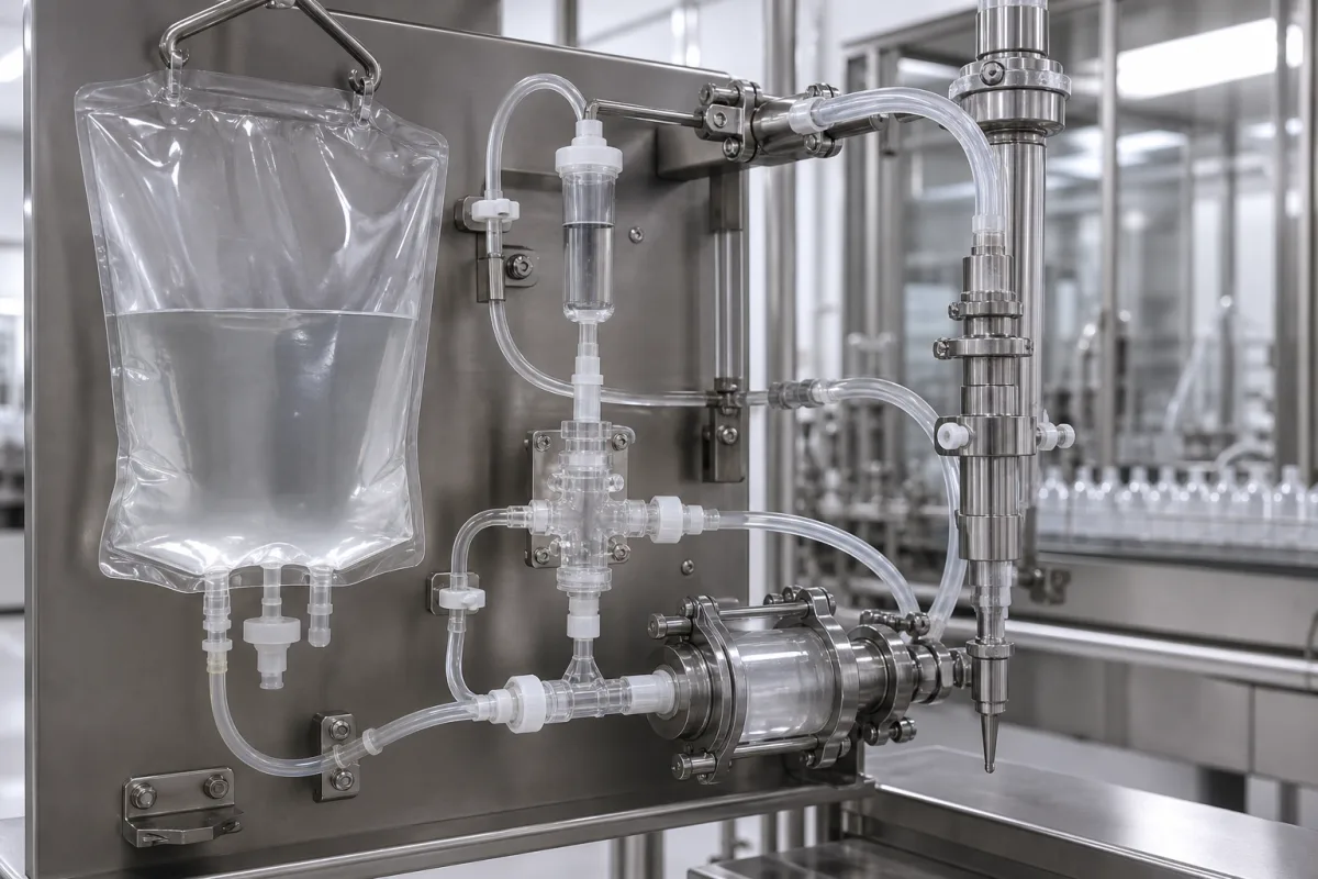
Representative product image. Confirm appearance and specifications with the manufacturer.

Product Specifications

Technical details and manufacturing context for Fluid Path Assembly

Definition
Fluid path assemblies are the complete wetted route that contains and directs liquid through a filling or dosing pump. A single-use fluid path normally combines preselected tubing, connectors, chambers, valves and outlet interfaces for one batch or campaign, while a reusable path uses cleanable metal or polymer components with validated seals and maintenance intervals. In a peristaltic design, rollers compress flexible tubing so the fluid contacts only the tube; in a piston design, a reciprocating piston and check valves create suction and discharge strokes. Procurement should define fluid chemistry, viscosity and particulates, 0.1–1,000 mL/min reference flow, accuracy and repeatability, 1–6.9 bar pressure, temperature, connection size, intended use mode, sterilization method and required material evidence. Published ranges are RFQ references; the legal manufacturer must confirm extractables, food-contact or biocompatibility evidence where applicable, sterilization compatibility, pressure integrity and fill performance for the actual assembly.
Working Principle
In a peristaltic fluid path, rotating rollers progressively compress flexible tubing and move a trapped volume from inlet to outlet without the pumped liquid contacting the rotor. In a piston path, the piston retracts to draw liquid through an inlet check valve and advances to discharge through an outlet valve. Tubing bore, pump speed, piston displacement, valve timing, backpressure and seal condition determine flow, repeatability and residual volume. Verification should use the intended liquid or a justified surrogate at the operating pressure, temperature and cycle rate, with gravimetric flow or dose measurements and a documented leak test.
Common Materials
316L stainless steel, PTFE or PEEK wetted parts, Platinum-cured silicone tubing
Technical Parameters
ParameterTypical rangeNotes & selection driver
Flow Rate Range0.1–1,000 mL/minReference range only; confirm with the intended liquid, tubing bore, pump geometry and speed.
Flow Accuracy±0.5–±1.0 % of set pointVerify gravimetrically under the specified liquid, backpressure, temperature and cycle conditions.
Repeatability±0.25–±0.5 %Confirm over the required number of cycles after priming and stabilization.
Max Operating Pressure1–6.9 barUse the lowest verified pressure rating of tubing, connectors, valves, seals and housing.
Fluid Temperature5–80 °CVerify material, seal and sterilization compatibility across the operating range.
Tubing MaterialPlatinum-cured silicone, PTFE or PEEKSelect from chemical compatibility, extractables, flex-life and sterilization requirements.
Wetted Materials316L stainless steel, PTFE, PEEK, EPDM or siliconeFinal selection depends on fluid chemistry, cleaning agents and intended-use evidence.
Connection Size1/8–1/2 inSpecify interface type, nominal size and required dead-volume limit.
Use ModeSingle-use or validated reusableDefine batch or campaign duration, cleaning strategy and replacement interval.
Sterilization MethodGamma irradiation or validated autoclave cycleUse only when supported by the selected material and manufacturer validation.
Compatible Pump Speed10–600 rpmReference range only; confirm against pump design, tubing life and required flow.

Ranges are indicative industry figures for RFQ preparation, not a supplier commitment. Confirm every value and standard with the legal manufacturer before ordering.

Components / BOM
  • Inlet Manifold/Port Part
    Directs fluid from the supply source into the pump's primary chamber or tubing.
    Material: Stainless Steel or Plastic
  • Pumping Chamber / Tubing Section Part
    In peristaltic pumps: the flexible tube compressed by rollers. In piston pumps: the cylinder where the piston reciprocates.
    Material: Silicone, PTFE, or Stainless Steel
  • Valve Assembly (Piston Pumps)
    Check valves (inlet and outlet) that ensure one-way flow during the suction and discharge strokes.
    Material: Stainless Steel, Ceramic, Plastic
  • Outlet Nozzle/Dispense Head
    The final interface that directs and often shapes the fluid stream for precise dispensing into containers.
    Material: Stainless Steel or Plastic
  • Seals and Gaskets Part
    Provide leak-proof connections between sub-components and to the pump housing.
    Material: EPDM, Viton, PTFE

Applied To / Applications

This component is essential for the following industrial systems and equipment:

Industrial Ecosystem & Supply Chain Structure

Complementary Systems
Downstream Applications
Specialized Tooling

Application Fit & Sizing Matrix

What Decides the Award
  • Required flow or dose range, accuracy, repeatability and acceptable residual volume
  • Fluid chemistry, viscosity, particulates and operating temperature
  • Single-use or reusable strategy, batch duration and cleaning or sterilization method
  • Maximum inlet pressure, discharge pressure and backpressure
  • Connection type, nominal size, routing envelope and dead-volume limit
  • Required material, lot-traceability and intended-use evidence
Failure Modes & Inspection
  • Tubing, seal or chamber leakage
    Check: Documented leak test at the specified operating condition and visual inspection after the defined cycle count
  • Flow drift or backflow
    Check: Gravimetric flow or dose verification after priming and stabilization
  • Sterilization damage or loss of material integrity
    Check: Review validated material evidence and inspect for brittleness, deformation, discoloration or seal damage

Reliability & Engineering Risk Analysis

Failure Mode & Root Cause
Loss of pressure integrity
Cause: Tubing fatigue, seal damage, incompatible chemistry, excessive backpressure or an incomplete connector engagement.
Dose or flow instability
Cause: Tubing relaxation, valve leakage, trapped air, changing viscosity or pump settings outside the verified range.
Cross-contamination or material degradation
Cause: An unsuitable cleaning or sterilization method, reuse beyond the validated campaign, or incomplete material traceability.
Maintenance Indicators
  • Visible weeping, bubbles, pressure decay or a loose connection
  • Increasing dose variation, residual volume or priming time
  • Tubing flattening, discoloration, brittleness, swelling or seal deformation
Engineering Tips
  • Select every wetted material against the actual fluid, temperature and sterilization method.
  • Define a priming procedure, verification interval and replacement limit in the operating record.
  • Use keyed or otherwise mistake-resistant connections and retain batch and lot traceability.

Indicative industry ranges for design and RFQ preparation. Confirm the exact figures and applicable standard with the manufacturer before specifying.

Compliance & Manufacturing Standards

Applicable Standards
ISO 10993 series — only where biological evaluation applies to the intended medical-device use USP <88> Class VI — only where supplier test evidence supports the specified polymer Applicable food-contact legislation — only for wetted materials intended for food use

Quoted from the published standard.

Manufacturing Precision
  • Pressure limit: the lowest verified rating of the tubing, connectors, valves, seals and housing governs
  • Flow accuracy and repeatability: verify with the intended liquid or a justified surrogate under specified conditions
Quality Inspection
  • Documented pressure-integrity or leak test
  • Gravimetric flow or dose verification
  • Material, sterilization and lot-traceability document review

Manufacturers of Fluid Path Assembly

Manufacturer profiles associated with Fluid Path Assembly.

Sourcing Fluid Path Assembly from China?
Tell us your specification and target quantity — we will match it against manufacturer records and come back with the factories that fit.
Request manufacturers We manufacture this

Manufacturer listings support early research and capability understanding. They are not certification, ranking, or transaction guarantees.

Technical documentation
Request current drawings, revision history, and a signed specification sheet.
Manufacturing capability
Verify equipment lists, process limits, capacity, and representative production evidence.
Inspection readiness
Confirm test methods, calibrated equipment, sampling plans, and traceable reports.
Supplier transparency
Check the legal entity, factory address, ownership, certifications, and direct contacts.

CNFX does not score or rank suppliers. Buyers must verify all claims and documents with the legal manufacturer before ordering.

Supply Chain Compatible Machinery & Devices

Hydraulic Press

Industrial machine using hydraulic pressure to compress, form, or assemble materials

Explore Specs →
Heavy-Duty CNC Plasma Cutting Machine

The Heavy-Duty CNC Plasma Cutting Machine is a standalone industrial device designed for cutting conductive metals such as steel, stainless steel, aluminum, and copper alloys.

Explore Specs →
Automated Powder Coating System

Integrated industrial system for applying dry powder coatings to metal substrates.

Explore Specs →
Centrifugal Pump Impeller

The centrifugal pump impeller is a critical rotating component that converts mechanical energy from the motor into kinetic energy in fluid systems.

Explore Specs →

Frequently Asked Questions

What is a fluid path assembly?

A fluid path assembly is the complete wetted route that contains and directs liquid through a filling or dosing pump. It includes tubing, chambers, valves, seals, and connectors, and can be designed for single-use or reusable applications.

What are the main design types?

Two common designs are peristaltic and piston. In peristaltic, rollers compress flexible tubing to move fluid without contacting the rotor. In piston, a reciprocating piston and check valves create suction and discharge strokes.

What parameters should be specified when procuring?

Define fluid chemistry, viscosity, particulates, flow rate range (0.1–1,000 mL/min reference), accuracy, repeatability, pressure (1–6.9 bar), temperature, connection size, use mode, sterilization method, and required material evidence.

Why is verification with the manufacturer necessary?

Published ranges are reference only. The legal manufacturer must confirm extractables, food-contact or biocompatibility evidence, sterilization compatibility, pressure integrity, and fill performance for the actual assembly and intended use.

Data Basis

Editorial classification, named public sources where available, and source-reviewed manufacturer records.

Preliminary Technical Classification
This page supports structured research, RFQ preparation, and supplier evaluation. It does not replace buyer-led supplier qualification, standards review, or technical approval.
Buyer enquiry

Request manufacturing insight for Fluid Path Assembly

Ask for use case, specification boundaries, supplier type, and RFQ preparation information for this product.

Where it goes
Straight to the CNFX editorial desk, and to the manufacturer if this product is linked to a claimed profile. Nothing is broadcast to a supplier list.
Your details stay here
We do not sell or rent enquiry data, and we do not add you to a mailing list. Used only to answer this request.
No commission, no middleman
CNFX is a directory. We take no cut of any order and never negotiate on a supplier's behalf.
What we don't claim
A listing is not an endorsement. Qualify every supplier and verify every figure yourself before ordering.

Your business information is used only to process this request.

Thank you! Your message has been sent. We'll respond within 1–3 business days.
Sorry, we couldn't send your message. Please try again, or email us at contact@cnfx.com.

Need to Manufacture Fluid Path Assembly?

Compare manufacturer profiles with relevant product and process capability.

Previous Product
Fluid End
Next Product
Fluid Port Connectors
Get QuotesChat