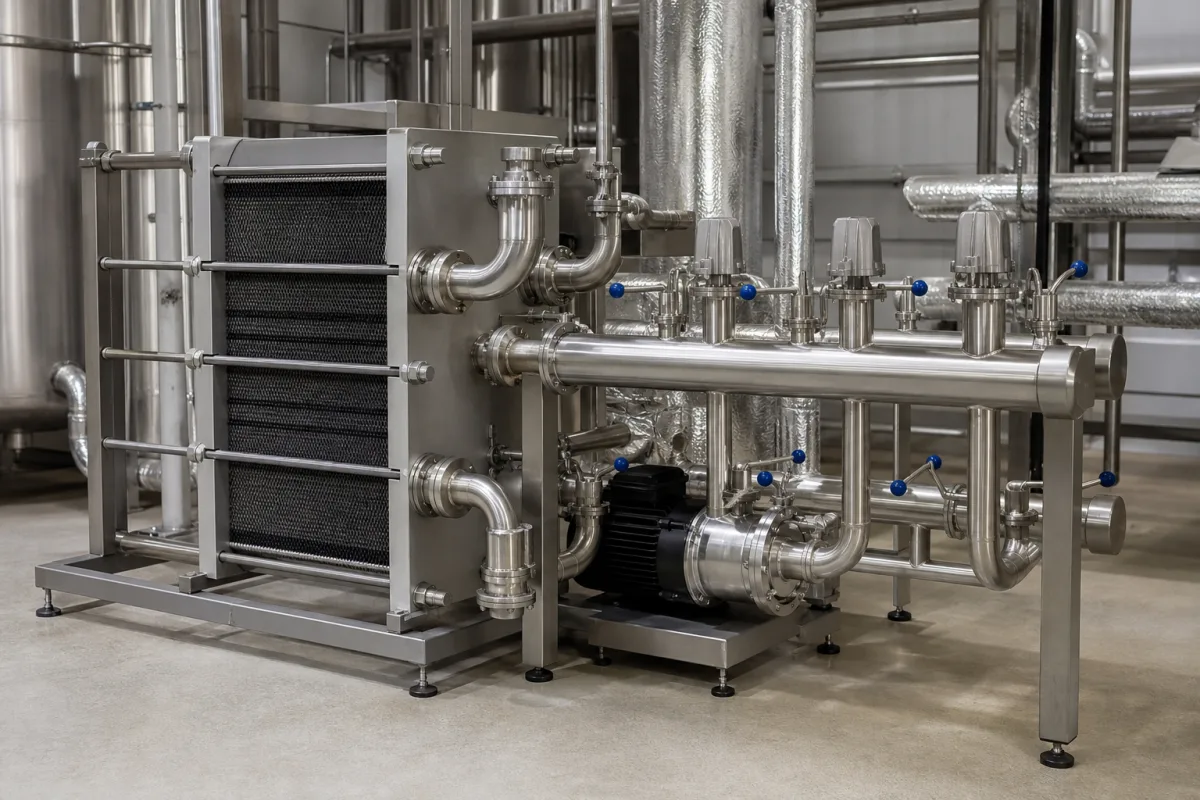
Indirect heating substation with secondary distribution: the plate exchanger, pumps and zone circuits between a district heating main and a building
Where a district heating main meets a building · a plate heat exchanger that separates the two water circuits, then pumps, control valves and a set of heating circuits on the secondary side, all held to a return temperature the heat network sets
A building connected indirectly to a district heating network never shares water with it: the network's hot water passes through one side of a plate heat exchanger and the building's own circuits through the other. The exchanger is only half of the job. Behind it sit circulation pumps, control valves, a heat meter and the branches that feed radiators, underfloor loops, fan coils and air-handling coils. Heat network operators judge the whole package by one number above all, the temperature of the water sent back to them, and write their connection rules around it.
Indirect heating substations for buildings on district heating or heat networks and the secondary distribution they feed: plate heat exchangers sized to the network's flow and return temperatures, differential pressure and control valves, heat meters, circulation pumps, and the radiator, underfloor, fan-coil and air-handling circuits behind them. The full range of industrial exchanger types is covered on the Heat exchanger page and the construction of gasketed plate units on the Gasketed plate-and-frame heat exchanger page; finned-tube cores are on the Heat Exchanger Core page, and hot- and chilled-water modules for process vessel jackets on the Temperature control module page.
CNFX editorial research · Sources checked October 13, 2026 · 4 sources
Exchanger temperatures a heat network writes into the connection: Tallinn's 80/≤43 °C and Hull's 65/40 °C with a 3 °C approach
Both utilities below size the plate exchanger from the return side: the water leaving the exchanger for the network may be only a few degrees warmer than the building's own return.
The Tallinn table gives these values at the design outdoor temperature and caps the primary return at 3 °C above the secondary return; Hull specifies its plate exchangers with a maximum 3 °C approach across the return lines and a maximum pressure drop of 80 kPa on the secondary side. [1][2] Editorial calculation: for a new Tallinn building that means 80 − 43 = 37 K or more of cooling on the network side against 60 − 40 = 20 K on the building side, so the network water flow is at most about 54 % of the building circuit flow for the same heat.
Utilitas requires an indirect connection for every automated substation, allows a two-stage exchanger where domestic hot water capacity exceeds 0.15 MW and the heating flow temperature is 70 °C or less, and bases the choice of material for the consumer installation on 130 °C and 1.6 MPa. Its primary side has to be steel P235. [1] Hull says two exchangers in parallel, each sized at 60 % of peak load, give a full thermal range with some redundancy for maintenance, and that larger substations may have more than two. [2]
Ask the network operator for the design primary supply and maximum return, the approach required, the differential pressure available, and the design pressure and temperature for materials before the exchanger is selected.
02
Behind the exchanger: four building circuits held under 40 °C return, staged pumps and two-port valves instead of low-loss headers
Hull's guide for designers draws the secondary side as a set of parallel circuits fed from one point of supply, each with its own two-port control and its own return limit:
The guide lists among its design principles avoiding low-loss headers, three-port valves and uncontrolled bypasses at circuit ends, giving higher return temperatures as the reason; any bypass needed for minimum pump flow is to be small bore and controlled to open only when the smallest pump is at its minimum. Secondary pumps are to be multiple staged variable-speed units in parallel, controlled on differential pressure across one or more index runs. [2]
For radiators the guide gives a sizing of 55 °C flow and 30 °C return as one that leaves a margin inside the 40 °C target. [2] Utilitas adds the monitoring side: substations above 0.15 MW that are not connected straight away to the building's central remote management system have to be ready for a Modbus TCP/IP or BACnet/IP style interface with return temperature sensors on each heating circuit, and those with domestic hot water above 0.15 MW need control that cuts heating flow during hot water peaks. [1]
List each building circuit with its emitter type, design flow and return temperatures and load, and say whether the pumps, valves and controls for those circuits are part of the substation package.
03
Packaged substation sizes: 14 to 50 kW wall units and plant rooms up to 2,000 kW
Danfoss's Termix VX-FI is a packaged indirect substation for houses with up to seven apartments: stainless steel plate exchanger brazed with copper, circulation pump, differential pressure controller, expansion tank, safety valve and fitting piece for a heat meter, PN 10 with PN 16 on enquiry and a maximum district heating supply of 120 °C. [3]
Editorial calculation: 14 kW across a 25 K secondary difference needs about 14 ÷ (4.18 × 25) × 3,600 ≈ 482 l/h of water, matching the 485 l/h listed; the primary flow of 415 l/h implies about 29 K of cooling on the network side. [3] The larger FI3 model reaches 50 kW at 90 °C primary supply. The same maker's Akva Lux II VXe HT combines indirect heating with instantaneous hot water at 25–50 kW heating and 35–75 kW hot water, rated for 130 °C supply with PN 25 on the primary side. [4]
At building scale the plant room grows with the connection. Hull's guidance gives a net floor area of 3 × 2 m and about 500 kg floor loading for connections up to 100 kW, rising to 6 × 5 m and 2,500 kg at 2,000 kW, with a 2.5 m height in every case. [2] After installation Utilitas pressure-tests the substation with cooled water at 10 bar (1 MPa) for 15 minutes in front of its representative, and asks for two heat meters in parallel where one would have to exceed DN100. [1]
Give the heating and hot water loads, the network temperatures and pressure class, the available plant room footprint and access route, and who supplies the heat meter.
04
What to send for an indirect heating substation
Paste it into your enquiry below or into an email to a maker, then replace every bracket.
Network: [primary supply and maximum return; differential pressure; pressure class]
Loads: [space heating kW; hot water kW; ventilation kW]
Circuits: [radiator, underfloor, fan coil, AHU; flow and return temperatures each]
Exchanger: [approach; secondary pressure drop; single or parallel units]
Controls: [two-port valves; weather compensation; BMS interface]
Site: [plant room size; access door; floor loading; heat meter supplier]
Explore company information and manufacturing capabilities, then discuss the scope of your project with a relevant supplier.
Share this page
Compiled and source-reviewed by the CNFX editorial team.
Each manufacturer above links to the page on that company's own website where the product is listed, with the date we checked it. How we source and review
· Page last updated 13 October 2026
Buyer questions
What return temperature does a district heating substation have to achieve?
Tallinn's utility requires the primary side to leave the exchanger at 43 °C or less for new buildings, and Hull asks for a maximum secondary return of 40 °C. [1][2]
Why do heat networks object to low-loss headers on the building side?
Hull's design guide lists avoiding low-loss headers, three-port valves and uncontrolled bypasses among its principles because they raise return temperatures. [2]
How large is a packaged substation for a small apartment building?
Danfoss's Termix VX-FI covers 14 to 50 kW of heating for up to seven apartments in an 800 × 530 × 375 mm insulated unit listed at 30 kg including cover and packing. [3]
Sources and what still needs a direct check
Sources checked 2026-10-13. Connection rules are from two heat network operators, AS Utilitas Tallinn (Estonia) and Hull City Council (UK); packaged substation data are from two Danfoss fact sheets.