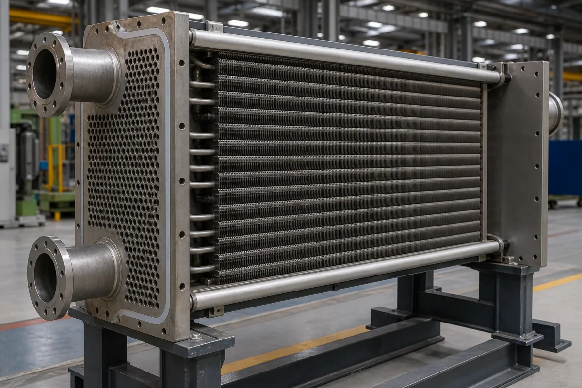
The core in the illustration is a frame of horizontal finned tubes between a drilled tubesheet with flanged nozzles and an end plate, held by tie rods. When one side of the duty is a gas, fins add surface on that side, and the core is chosen by how the fin is fixed to the tube, what shape the fin has, and how close the tubes sit. Each of those decides a temperature limit, a pressure drop or a cleaning interval.
Covers the finned-tube core of gas-to-liquid heaters, coolers, economisers and air-cooled exchangers: fin-to-tube bond types and their temperature and corrosion limits, plain versus serrated spiral fins, fin pitch, transverse tube pitch, tip clearance and external fouling. Plain tube bundles for shell-and-tube exchangers (tube layout, baffles, tubesheet joints) are on Tube bundle; choosing among exchanger types is on Heat exchanger; plate-type air-to-air ventilation recovery cores are outside this page.
CNFX editorial research · Sources checked October 12, 2026 · 3 sources
Golden Sunbird Metals' finned-tube page lists five ways of putting a spiral fin on a tube, each with a maximum working temperature and corrosion and mechanical ratings.
The limits follow the bond. A tension-wound L fin relies on contact pressure between foot and tube (editorial reading: that contact can loosen as tube and fin expand by different amounts); knurling (KL) keys the foot to the tube, and embedding (G) locks it into a groove so heat transfer holds at high tube-metal temperature. The extruded fin has no separate joint because it is formed from the outer tube itself.
Corrosion runs the other way for G fins: the groove exposes the base tube, rated low for atmospheric corrosion, whereas the overlapped LL foot and the extruded sleeve cover it. The supplier notes LL is used in corrosive service as a cheaper alternative to extruded fin.
Fin type
How the fin is held
Max working temp.
Atmospheric corrosion resistance
Mechanical resistance
Fin materials
L
Strip wound under tension; fin foot pressed on the tube
150 °C
Medium
Low
Aluminium, copper
LL
As L, but the foot overlaps to enclose the tube fully
180 °C
High
Low
Aluminium, copper
KL
As L, tube knurled first and the foot knurled into it
260 °C
Medium
Medium
Aluminium, copper
G (embedded)
Fin wound into a machined groove, locked by back-filling tube metal
400 °C
Low
Medium
Aluminium, copper, carbon steel
Extruded
Fin rolled out of an aluminium outer tube over the base tube
285 °C
High
High
Aluminium
These are one supplier's ratings; other suppliers quote different figures for the same types. Ask for the maximum tube-metal temperature at which the offered fin type is rated, not the gas temperature.
02
Plain or serrated spiral fin
Keawkamrop et al. (Case Studies in Thermal Engineering 35, 2022, KMUTT) tested plain and serrated welded spiral fins on 25.4 mm tubes with 50.0–51.0 mm fin diameter, 1.2 mm fins and two staggered rows.
A serrated fin moved more heat per tube than a plain one at the same pitch; the price is pressure drop, which climbs with deeper serrations and tighter pitch. The paper also reports that tube arrangement had no large effect on heat transfer in its tests.
Fin pitch in fins per inch converts as 25.4 / fpi: 7 fpi is 3.63 mm, 5 fpi 5.08 mm, 3 fpi 8.47 mm (Editorial calculation, matching the paper's values).
Variable tested
Values
Effect reported
Fin pitch
3.63 mm (7 fpi), 5.08 mm (5 fpi), 8.47 mm (3 fpi)
Heat duty and pressure drop rise as pitch falls; pitch affects friction and Euler number more than segment height
Segment (serration) height
2.50, 4.50, 6.50 mm
Heat duty and pressure drop rise with segment height; 6.50 mm gave the highest duty at every pitch
Plain vs serrated
Same pitch
Serrated fins gave a higher air-side heat transfer coefficient
Frontal air velocity
2–7 m/s
Duty, coefficient and pressure drop all rise with velocity
Ask the supplier for air-side heat transfer and pressure drop at your face velocity for both plain and serrated options, not one alone.
03
Tube pitch, tip clearance and fouling
Swart and Ellmer (Heat Exchanger Fouling and Cleaning conference, 2024) analysed more than 120 airflow measurements on more than 16 air-cooler bundles, before and after external cleaning.
They define a 2-D tightness T = (half the fin-circle area) ÷ (the triangular pitch area), and a fouling factor = static pressure corrected to design airflow ÷ design static pressure. Up to T = 0.73 the fouling factor stayed around 1 before and after cleaning. At 0.76 (1.5 in tube, 3 in pitch) the pre-cleaning factor reached 1.5. Above 0.76, fouling before and after cleaning rose to more than three times design.
Their explanation is that particles bridge the gap between adjacent tubes and block airflow, whereas on open bundles deposits stay around each tube's fins. Thermal ratings of four real air-coolers in HTRI showed negligible performance gain from tighter pitch; the main benefit was a smaller bundle. They also observed serrated fins causing excess air-side pressure drop and holding fouling in the serration pockets, making them hard to clean conventionally.
Their recommendation: avoid T above 0.76, such as 1 in tubes on 2⅜ in pitch, which corresponds to fin tip clearances of 3.2 mm or less; tight bundles only make sense in very clean, space-limited plants, and existing tight bundles need fans with spare static pressure and more frequent cleaning.
Tube OD
Fin OD (15.875 mm fins)
Transverse pitch
Tip clearance
Tightness T
25.4 mm (1 in)
57.15 mm
60.33 mm (2⅜ in)
3.18 mm
0.81
38.1 mm (1.5 in)
69.85 mm
76.2 mm (3 in)
6.35 mm
0.76
38.1 mm (1.5 in)
69.85 mm
84.7 mm
14.85 mm
0.61
Editorial calculation of fin OD (tube OD + 2 × fin height), clearance (pitch − fin OD) and T from the paper's formula; the results match the paper's table. Give the supplier the site's dust conditions and ask for T and tip clearance with the offer.
04
What to specify for a finned-tube core
Paste it into your enquiry below or into an email to a maker, then replace every bracket.
State the gas and its maximum temperature, the tube-side fluid and design pressure, the maximum tube-metal temperature, the site atmosphere (marine, chemical, dusty), face velocity and allowable air-side pressure drop, and how the core will be cleaned. Ask for fin type and bond, fin and tube materials, fin height, thickness and pitch, plain or serrated, tube OD and transverse pitch with the resulting tip clearance, and air-side heat transfer and pressure drop at design velocity.
Explore company information and manufacturing capabilities, then discuss the scope of your project with a relevant supplier.
Share this page
Compiled and source-reviewed by the CNFX editorial team.
Each manufacturer above links to the page on that company's own website where the product is listed, with the date we checked it. How we source and review
· Page last updated 13 October 2026
Buyer questions
Which fin type takes the highest temperature?
In Golden Sunbird Metals' table the embedded G fin is rated to 400 °C, extruded to 285 °C, KL to 260 °C, LL to 180 °C and L to 150 °C. [1]
Do serrated fins transfer more heat than plain fins?
In Keawkamrop et al.'s tests serrated welded spiral fins gave a higher air-side heat transfer coefficient than plain ones at the same pitch, with higher pressure drop as serration height grew. [2]
How tight can the tube pitch be before fouling runs away?
Swart and Ellmer recommend keeping 2-D tightness at or below 0.76, avoiding fin tip clearances of 3.2 mm or less; above 0.76 fouling exceeded three times design. [3]
Are serrated fins harder to clean?
Swart and Ellmer observed fouling collecting in the serration pockets, making such bundles hard to clean by conventional methods. [3]
Sources and what still needs a direct check
Sources checked 2026-10-12. A finned-tube supplier's fin-type table, a peer-reviewed conference paper on air-cooler fouling and a peer-reviewed experimental study of serrated fins.